




Solder paste tack time concerns how long printed paste retains useful adhesive holding ability before reflow. It is not interchangeable with shelf life or stencil life. When a component moves, first establish whether it was misplaced initially, disturbed during handling, or shifted only during heating. A paste data-sheet number alone cannot distinguish those events.
This guide focuses on placement delays and pre-reflow movement. Use it to prepare a controlled trial or an assembly review, not to assign a universal overnight waiting allowance.
What does solder paste tack time mean?
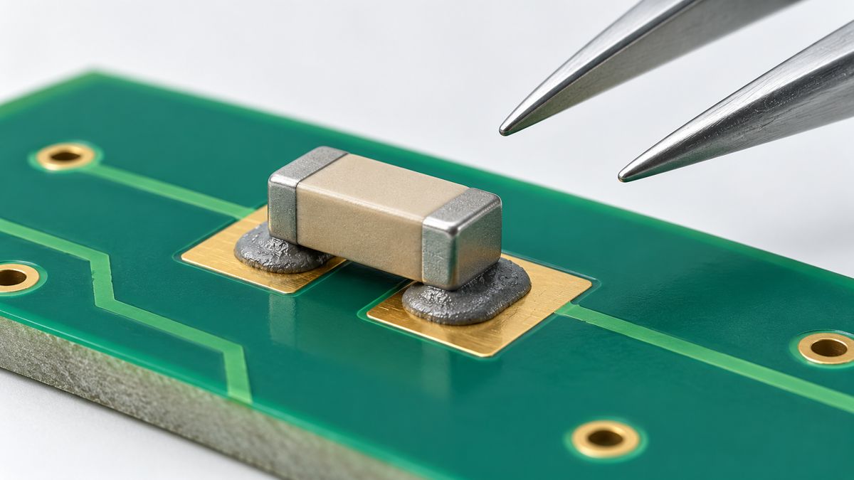
Tack is the adhesive force that helps retain a component after placement and before a solder joint exists. Tack retention describes how that behavior changes as a printed deposit waits. The useful production window depends on the paste, deposit, component and handling process together.
A small part sitting undisturbed is not the same challenge as a tall component passing through a transfer. Conversely, a part that appears secure does not prove that the paste will wet correctly during reflow. Keep placement retention and solder-joint acceptance as separate checks.
Tack time vs stencil life vs shelf life: what is the difference?
| Property | What it describes | What it does not establish | Evidence to request |
|---|---|---|---|
| Tack retention | Adhesive behavior of a printed deposit as it ages | Reliable holding of every package during every transfer | Time-dependent results, test conditions and board trial |
| Stencil life | Usability during the specified printing conditions | An identical print-to-placement or print-to-reflow allowance | Printing conditions, interruptions and supplier limits |
| Shelf life | Storage allowance for the stated packaging and temperature | Usability after uncontrolled opening or exposure | Lot, expiry and storage history |
| Validated assembly window | The allowed timeline for a particular build and process | Transferability to a different paste, board or handling route | Trial records and release criteria |
For container handling and expired material, use the separate solder paste storage guide. For deposits spreading into neighboring lands, investigate solder paste slump. Neither symptom should automatically be called a tack failure.
How is solder paste tack measured?
The published IPC-TM-650 2.4.44 method, dated March 1998, measures the force needed to separate a probe from printed paste. It repeats measurements after different waiting periods and averages at least six readings per time point. The time-dependent curve is more informative than one initial force value. The method includes an 80%-of-peak evaluation option; that is not a universal assembly acceptance limit.
Ask a supplier to identify the method revision, conditioning, delay times and reporting units. Do not convert a probe result into an allowable component weight. A probe contact and a component termination have different contact geometry and loading. Compare reports only after their conditions are aligned.
AMTECH NWS-4400-HA-LF: which parameters matter?
The manufacturer’s NWS-4400-HA-LF PDS2025-EN provides a useful example of why separate specifications matter. These are product-specific published values, not PCBtry process guarantees.
| Published parameter | Value and conditions | Interpretation limit |
|---|---|---|
| Tack value | 34 g, IPC-TM-650 2.4.44 | No tolerance or retention curve is stated alongside it; not a guaranteed minimum or a 34 g component rating |
| Stencil life | More than 8 hours at 30–45% RH and 20–25°C | Printing specification, not a board waiting allowance |
| Stencil life at higher humidity | Approximately 4 hours at 45–75% RH and 20–25°C | Do not extrapolate beyond the stated conditions |
| Refrigerated shelf life | Six months at 3–8°C | Storage condition, not tack retention |
| Unopened room-temperature shelf life | One month at 25°C | Not permission to leave printed boards for a month |
For purchasing, identify the exact alloy, powder type and print or dispense grade as well as the product family. Ask for the applicable handling instructions and a board-level waiting-window recommendation. A single tack number does not answer that question.
Why do components move before reflow?
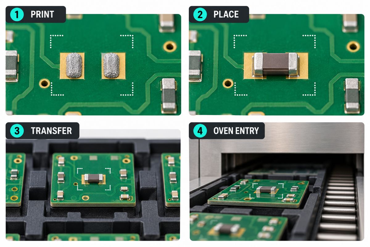
Locate the first observable change. If the part is already offset immediately after placement, inspect the placement coordinates, rotation, seating and paste deposit before changing material. If it is correct after placement but wrong after transfer, inspect the support and handling event. If it stays correct through oven entry, investigate the thermal and wetting process rather than labeling the event a room-temperature tack problem.
Use the same identifiable component locations in each photograph. Record orientation and scale so that camera angle does not masquerade as movement. A useful comparison has both a short-wait control and the actual delayed route, while holding the board revision, stencil, paste lot and placement setup constant. Change one suspected cause at a time; otherwise an improvement cannot be attributed confidently.
How can you control long placement delays?
- Prepare before printing. Verify the BOM, placement map, component orientation and part kits before exposing the first printed board to the waiting period.
- Set the clocks explicitly. Record print completion, first placement, last placement and oven entry. A statement such as “two hours on the bench” is ambiguous without these events.
- Match batch size to capacity. Print only the number of boards that the available placement and reflow route can handle within the qualified window. Include inspections and interruptions in that estimate.
- Define a hold decision. When the approved interval is exceeded, identify and segregate the affected boards. Obtain a documented disposition instead of silently resetting the timer.
- Verify the outcome. Check component position and the required solder-joint acceptance criteria after the trial. Passing a pre-reflow retention check is not a substitute for the reflow and inspection process.
For example, a board that takes 90 minutes to populate and waits another 30 minutes before the oven has a two-hour print-to-reflow interval only if placement began immediately after printing. This is an arithmetic example, not a recommended paste limit. A queue before placement makes the interval longer.
What should you record before changing solder paste?
Copy this matrix into the build traveler. Add your actual timestamps and acceptance references; do not fill it with assumed “pass” results.
| Checkpoint | Record | Decision enabled |
|---|---|---|
| After printing | Time, paste lot, product/grade, room conditions, deposit image, stencil revision | Separate an initial deposit problem from later change |
| After placement | Start/end times, reference designators, position images, interruptions | Establish whether parts were correctly seated initially |
| After transfer / before oven | Time, handling route, board support, same-location images | Identify movement before heating |
| After reflow | Profile reference, position and joint inspection results, disposition | Separate retention findings from reflow defects |
Need to review an assembly delay or recurring movement? Send PCBtry the BOM, CPL, assembly drawing, paste identification, timing log and before/after photographs through the contact page. Specify the affected reference designators and the expected production quantity so the PCB assembly review can address the actual build. Confirm any specialist material testing separately.
Solder paste tack time FAQ
How long can printed solder paste hold components before reflow?
There is no single duration for all pastes and assemblies. Obtain the exact product guidance and validate the longest planned delay with the actual packages and handling route. Record print-to-placement and print-to-reflow separately.
Does eight-hour stencil life mean eight hours of tack on the PCB?
No. Stencil life describes a different condition and performance requirement. Ask specifically for printed-deposit tack retention or an assembly waiting recommendation rather than transferring the stencil value to the board.
Can I resume placement after leaving a board overnight?
Only an applicable qualified process can authorize that delay. If the window is unknown or exceeded, hold the board for disposition. An anecdote that the paste later melted does not establish acceptable joints or long-term reliability.
Why does a tall component fall over when smaller parts stay in place?
Package geometry, seating, deposit contact and the disturbance may differ. Inspect the affected component immediately after placement and after each transfer. Do not conclude that the entire paste lot has failed from that observation alone.
Will reflow pull a displaced component back into position?
Do not rely on that as a repair strategy. Stop and assess the placement against the assembly requirements before heating. A visibly misplaced component can create defects that reflow does not correct.
Can I add flux or alcohol when the deposits stop feeling sticky?
Do not improvise a material modification. It changes the controlled formulation and can obscure the cause. Follow a documented supplier-approved process or the approved clean-and-reprint disposition.
Should I print fewer boards when hand placement is slow?
That is a useful scheduling option: compare total placement, inspection and queue time against the validated window. Prepare parts first, and avoid printing a batch that cannot reach reflow within the allowed timeline.
What should I ask a paste supplier about tack time?
Provide the exact grade, package mix, deposit geometry, environment and maximum delay. Request time-dependent tack information and its test conditions, then agree how those results will be checked on your assembly.
For a production review, send the timing log and assembly files with the defect photographs. Keeping the observations together is more useful than requesting a “stickier paste” without a documented failure stage.



0 Comments