




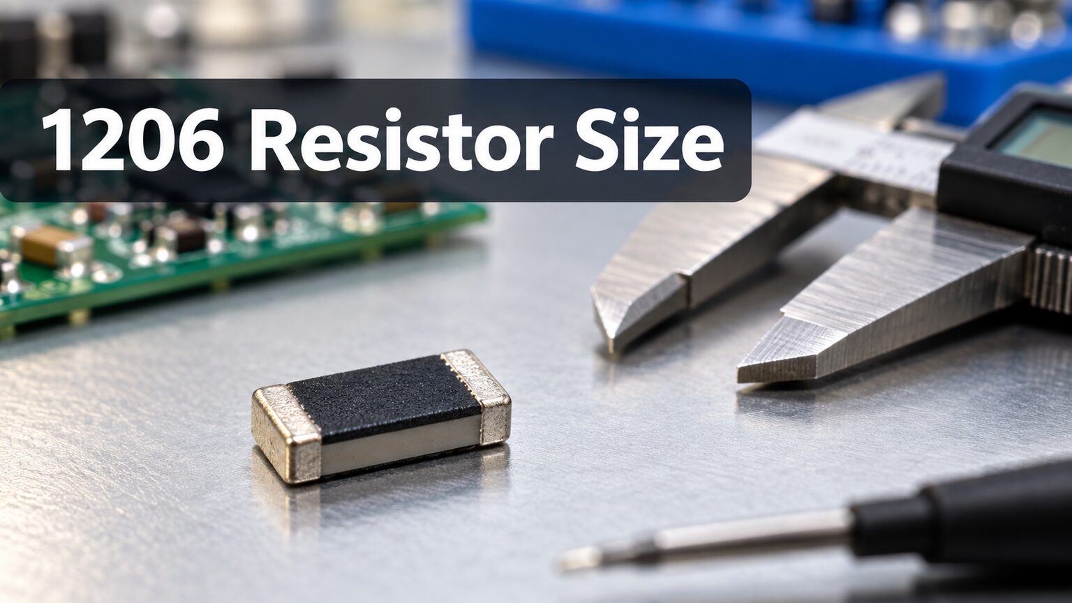
A 1206 resistor has a nominal imperial footprint of 0.12 × 0.06 inches, corresponding to the 3216 metric code and approximately 3.2 × 1.6 mm. That code identifies the length and width class—not a universal body height, power rating, voltage limit, resistance range or land pattern.
For example, Vishay specifies its D25/CRCW1206 thick-film resistor at 3.2 +0.10/-0.20 mm long, 1.6 ±0.15 mm wide and 0.55 ±0.05 mm high. Another 1206 series may use different tolerances, height, terminals, construction or ratings. Use the exact manufacturer part number and datasheet before releasing a footprint or BOM.
What Does the 1206 Resistor Size Code Mean?
The four-digit imperial code uses the first two digits for nominal length and the last two for nominal width in hundredths of an inch. Therefore, 1206 means about 0.12 inches long and 0.06 inches wide. The corresponding metric code is 3216, representing about 3.2 × 1.6 mm.
The code is a package-size label, not a resistance marking. A component marked “1206” in a catalog filter may be a resistor, capacitor, inductor, fuse or jumper with that nominal outline. Its electrical function and value must be identified from the complete MPN, reel label, BOM or manufacturer documentation.
1206 Resistor Dimensions and Tolerances
The useful engineering answer is a nominal 3.2 × 1.6 mm outline plus the tolerances in the selected datasheet. Height and termination geometry are series-specific.
| Dimension Item | 1206 Reference | Engineering Meaning |
| Imperial code | 1206 | Nominal 0.12 × 0.06 inch length and width class |
| Metric code | 3216 or RR3216M | Nominal 3.2 × 1.6 mm length and width class |
| Vishay CRCW1206 length | 3.2 +0.10/-0.20 mm | Use the asymmetric tolerance when checking courtyard and assembly clearance |
| Vishay CRCW1206 width | 1.6 ±0.15 mm | Actual body width can differ from the nominal 1.6 mm |
| Vishay CRCW1206 height | 0.55 ±0.05 mm | Height is not encoded by “1206” and must be checked by series |
| Terminal dimensions | Series-specific | Affect solder fillet, toe extension and land-pattern choice |
The Vishay values above apply to one documented thick-film family. They are a worked reference, not a universal mechanical specification for every 1206 resistor.
1206 vs 0805, 0603 and 1210
1206 is longer and wider than 0805 and 0603, while 1210 has the same nominal length as 1206 but is wider. Package size affects board area, assembly handling and thermal behavior, but it does not alone determine electrical capability.
| Imperial Size | Metric Code | Nominal Body Size | Selection Note |
| 0603 | 1608 | 1.6 × 0.8 mm | Smaller area; typically lower dissipation and harder manual handling, subject to series |
| 0805 | 2012 | 2.0 × 1.25 mm | Compact general-purpose size; not footprint-compatible with 1206 |
| 1206 | 3216 | 3.2 × 1.6 mm | More area for handling and thermal spreading than smaller sizes |
| 1210 | 3225 | 3.2 × 2.5 mm | Same nominal length as 1206 but substantially wider; requires a different land pattern |
| 2010 | 5025 | 5.0 × 2.5 mm | Larger outline often used when a suitable series needs more dissipation or pulse capability |
These dimensions describe nominal package classes. Always check the selected series because manufacturers publish their own body and termination tolerances.
Does Every 1206 Resistor Have the Same Power Rating?
No. A common general-purpose 1206 thick-film resistor may be rated around 0.25 W under specified conditions, but higher-power, pulse-resistant, current-sense, thin-film and specialty constructions can differ. Package size is only one input to power capability.
Vishay lists 0.25 W at 70 °C for the referenced CRCW1206 family and a 200 V operating-voltage reference under its stated conditions. These figures must not be transferred to a different manufacturer or series. Actual allowable power is limited by ambient temperature, board thermal resistance, mounting, resistance value, maximum working voltage, film temperature and derating curve.
For a resistor with resistance R, the idealized relations are P = I²R and P = V²/R. The design limit is the lowest applicable restriction from rated power, working voltage, current, pulse energy, temperature and reliability margin—not whichever calculation produces the largest number.
Non-Negotiable 1206 Selection Rules
Use these rules before approving a 1206 resistor for design-in:
- Rule 1: select the exact MPN. “1206 resistor” is incomplete; include manufacturer, series, resistance, tolerance, TCR, power, packaging and qualification suffixes.
- Rule 2: separate typical values from guaranteed limits. Do not treat nominal dimensions, typical drift or marketing summaries as Min/Max guarantees.
- Rule 3: check the derating curve. Rated power at 70 °C does not mean the same power is allowed at the maximum operating temperature.
- Rule 4: check voltage as well as power. A high resistance can reach the working-voltage limit before reaching nominal wattage.
- Rule 5: verify pulse and surge separately. Continuous power rating does not establish short-pulse, repetitive-pulse or overload capability.
- Rule 6: use the exact footprint recommendation. Do not copy a generic 1206 land pattern without checking termination geometry and assembly process.
- Rule 7: verify environment and qualification. Automotive, high-sulfur, high-voltage, precision and high-reliability applications may require a specific construction or qualification.
1206 Footprint and Assembly Checklist
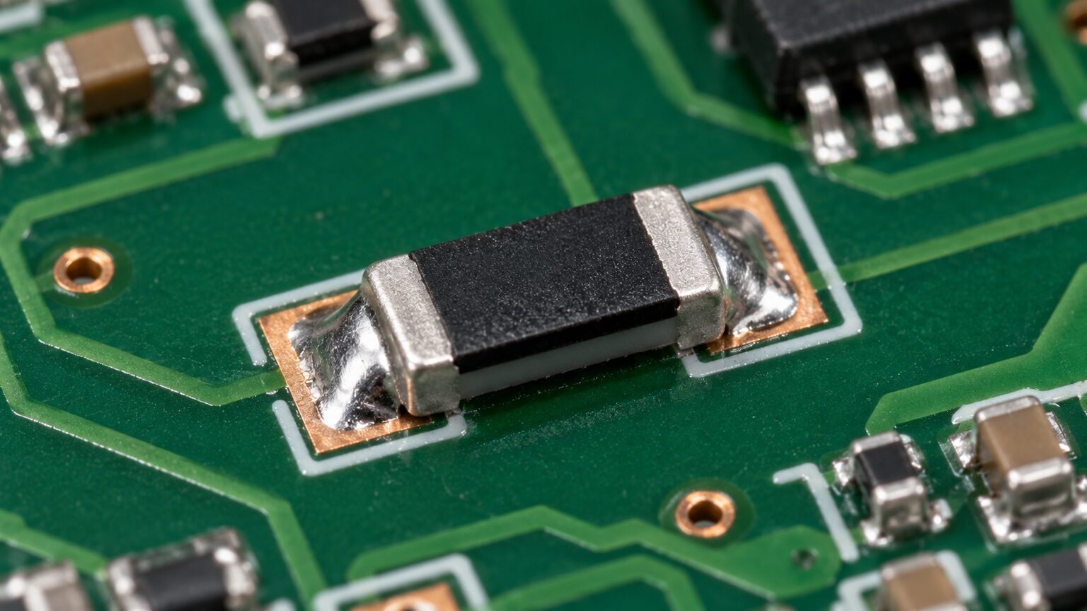
A 1206 footprint should be based on the component datasheet, the assembly process and the applicable land-pattern standard. A generic footprint can be a starting point, not final proof.
- Confirm body, terminal and height tolerances from the exact series.
- Use the manufacturer’s reflow or wave-solder land pattern for the intended process.
- Check solder-mask opening, paste aperture and component courtyard with the assembler.
- Keep pad geometry symmetrical to reduce tombstoning and uneven wetting risk.
- Allow thermal spreading when the resistor operates at meaningful dissipation.
- Avoid placing a hot resistor beside temperature-sensitive components or under an enclosure hot spot.
- Review board flex and mechanical stress, especially near panel edges, connectors and mounting points.
- Verify cleaning, coating and environmental compatibility for the resistor series.
Vishay’s referenced CRCW1206 data sheet provides different example dimensions for reflow and wave soldering, reinforcing that one footprint should not be copied blindly across every process.
Can You Replace 1206 with 0805 or 1210?
Not as a direct drop-in replacement. An 0805 is shorter and narrower, while a 1210 is wider. Even if improvised soldering is physically possible, the land pattern, solder-joint geometry, inspection criteria, power, voltage, pulse behavior and approved BOM change.
| Replacement Check | Why It Matters | Release Requirement |
| Body and terminal dimensions | Determine fit and solder-joint geometry | Compare manufacturer drawings and approved footprint |
| Resistance, tolerance and TCR | Affect circuit accuracy and drift | Meet the full operating range, not only nominal resistance |
| Power and derating | Package and construction affect temperature rise | Verify at worst-case ambient and board conditions |
| Working and overload voltage | High-value resistors may be voltage-limited | Check continuous and transient limits |
| Pulse capability | Nominal wattage does not define pulse survival | Use the applicable pulse-load curve or test evidence |
| Qualification and environment | Automotive, sulfur and reliability requirements can differ | Match required qualification and material declaration |
| Lifecycle and supply | A technically suitable part may be NRND or EOL | Check manufacturer product status and current supply evidence |
For reference only. Verify electrical, mechanical, thermal, compliance and lifecycle compatibility before design-in.
Common 1206 Resistor Mistakes and Root Causes
- Resistor runs too hot: nominal wattage was used without board-level thermal analysis or temperature derating.
- Unexpected open circuit: pulse energy, overload, board flex or solder-joint stress exceeded the selected series capability.
- Wrong measured value: the top marking was decoded incorrectly, an E96 code was mistaken for a direct value, or the reel label did not match the BOM.
- Assembly defects: pad symmetry, paste volume, placement or thermal balance was unsuitable for the process.
- Field drift: temperature, humidity, sulfur exposure or long-term load conditions were outside the intended resistor construction.
- Replacement failure: package size matched, but voltage, pulse, TCR, qualification or terminal construction did not.
Frequently Asked Questions
What is the 1206 resistor size in millimeters?
The nominal size is approximately 3.2 × 1.6 mm, also called 3216 metric. Exact length, width, height and terminal tolerances depend on the manufacturer and series.
What is the 1206 resistor size in inches?
The code represents a nominal 0.12 × 0.06 inch outline. It is a size class, not a calibrated measurement of every component.
Is 1206 the same as 3216?
Yes, they refer to the same nominal length-and-width class: 1206 is the imperial code and 3216 is the metric code.
How tall is a 1206 resistor?
Height is not encoded in “1206.” The referenced Vishay CRCW1206 is 0.55 ±0.05 mm high, but another series may differ.
Is every 1206 resistor rated at 0.25 W?
No. 0.25 W is common for some general-purpose series, but rated power varies with construction, manufacturer, operating mode and test conditions.
What voltage can a 1206 resistor handle?
There is no universal voltage. Vishay lists 200 V for the referenced CRCW1206 family under stated conditions, but the exact datasheet and resistance value control the design limit.
Can a 1206 resistor replace an 0805?
Not directly. The body and footprint differ, and power, voltage, pulse and qualification requirements must be revalidated.
Can a 1210 resistor use a 1206 footprint?
It should not be assumed. Both have a nominal 3.2 mm length, but 1210 is about 2.5 mm wide instead of 1.6 mm, so its land pattern and clearance differ.
Does the 1206 code show resistance value?
No. It only describes nominal package size. Resistance value comes from the component marking, MPN, reel label or BOM.
Which footprint should be used for a 1206 resistor?
Use the recommended land pattern for the exact series and soldering process, then confirm it against the assembler’s paste, mask, courtyard and inspection rules.
1206 Resistor Design Review and Source References
Before releasing a design, record the complete MPN, resistance, tolerance, TCR, power mode, voltage limit, pulse requirement, qualification, package drawing, footprint source and lifecycle status. The primary dimensional and rating example in this guide comes from the Vishay D/CRCW e3 thick-film chip resistor data sheet.
If your 1206 selection is part of a new board build and you need the component footprint checked against the BOM and assembly files, review the available PCB design support or contact PCBTRY at sales@pcbtry.com. Include the complete MPN, quantity, project stage, required delivery date and any non-negotiable electrical or compliance conditions.


0 Comments