




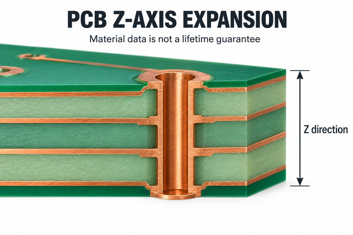
PCB Z-axis CTE describes how quickly a laminate expands through its thickness as temperature changes. It matters because a plated hole joins layers that move during heating. Selecting a higher glass transition temperature, or Tg, does not by itself establish that those connections will survive assembly and service.
Start with the material’s expansion data, then check the actual board construction and thermal history. The comparison and RFQ checklist below help turn a laminate data sheet into questions a fabricator can answer before you release a stackup.
What Does PCB Z-Axis CTE Mean?
CTE is a rate of dimensional change per degree of temperature change. For a PCB, X and Y lie along the board surface; Z passes from one face to the other. Always check the axis: an in-plane figure cannot substitute for a through-thickness figure when reviewing a plated-hole connection.
A value in ppm/°C means parts per million per degree Celsius. It is not a percentage and is not a maximum operating temperature. For example, an assumed constant 50 ppm/°C over a 100°C rise corresponds to 0.5% free expansion. Whether a real board follows that estimate depends on the temperature interval and construction.
Data sheets often separate a coefficient below Tg from one above Tg. They may also report total Z expansion over a stated interval, such as 50 to 260°C. Read all three with their conditions. Do not compare a coefficient from one supplier with total expansion from another as though the units were interchangeable.
High Tg vs Low CTE: Which Helps Via Reliability?
High Tg and low CTE answer different questions. Tg identifies a material transition; CTE describes dimensional response. Neither alone is a finished-board lifetime rating.
| Selection approach | What it tells you | What remains unknown | Useful next check |
|---|---|---|---|
| Choose by high Tg alone | Where the measured transition occurs | Expansion on each side of that transition | Compare both CTE values and total expansion |
| Choose by low pre-Tg CTE | Expansion rate within the stated lower-temperature region | Behavior through assembly temperatures | Check the upper-temperature region and assembly profile |
| Choose by low total Z expansion | Accumulated dimensional change across a specified interval | Via interface quality and service-cycle endurance | Qualify the actual stackup and interconnect structure |
| Choose by finished-board qualification | Performance of tested samples under a defined procedure | Untested constructions or altered processing | Control changes and define sampling limits |
A useful primary explanation is the Eurocircuits and imec discussion of thermal cycling: expansion mismatch, hole construction and thermal history must be considered together. Its historical process-specific cycle limits are not transferable to another manufacturer’s board.
Before paying for a different laminate, identify the failure you are trying to prevent. An intermittent interconnect needs a different investigation from a visible surface blister. A material change can reduce one stress contributor without correcting an interface defect or an unsuitable via structure.
What Do Isola 370HR and 185HR Parameters Show?
The Isola 2025 product guide, printed pages 20-21, lists the following values. These are manufacturer reference data, not PCBtry acceptance limits or evidence that either grade is currently stocked.
| Property | 370HR | 185HR | Condition to preserve |
|---|---|---|---|
| Tg | 180°C | 180°C | Use the applicable material test method |
| Pre-Tg Z-axis CTE | 45 ppm/°C | 40 ppm/°C | Below the transition |
| Post-Tg Z-axis CTE | 230 ppm/°C | 220 ppm/°C | Above the transition |
| Total Z expansion | 2.8% | 2.7% | 50 to 260°C |
The same listed Tg does not imply the same expansion. The summary does not specify a guaranteed tolerance or the exact specimen construction for these entries. Obtain the applicable data sheet, test conditions and agreed limits before using them as purchasing criteria. A small reference-value difference is not proof of longer via life.
Keep the material identity attached to your comparison. A quote that merely says “high-Tg FR4” has not identified the resin system or the construction that will be supplied. For the manufacturing context behind these choices, see the laminate manufacturing process.
How Do You Estimate Thickness Expansion?
A simple free-expansion estimate is useful for checking units, not for predicting copper stress or cycles to failure. Use a constant coefficient only inside the temperature region for which that assumption is reasonable.
Example with hypothetical inputs: assume a 1.6 mm thickness, a constant Z coefficient of 50 ppm/°C and a rise from 25 to 125°C entirely below the relevant transition. The estimate is:
Thickness change = 1.6 mm x 50 x 10^-6 /°C x 100°C = 0.008 mm = 8 micrometers.
With those same assumptions, 3.2 mm gives 0.016 mm. This demonstrates thickness scaling, not a conclusion that a thicker board has half the life. Real copper restraint, resin distribution and local interfaces are absent from this calculation.
- Write the starting thickness and temperature interval next to the calculation.
- Check whether the interval crosses Tg. If it does, a single lower-temperature coefficient is unsuitable.
- For an initial piecewise estimate, separate the lower and upper intervals and sum their expansions. Identify the assumed transition and coefficients.
- Prefer measured total expansion over the same interval for material screening when available.
- Do not convert the result into a pass/fail limit without a justified qualification requirement.
Also avoid using a listed Tg from one measurement method as an exact breakpoint for a different test. Request the underlying method when comparing suppliers. A few apparently precise decimal places do not repair incompatible inputs.
What Should a Thermal Qualification Plan Include?
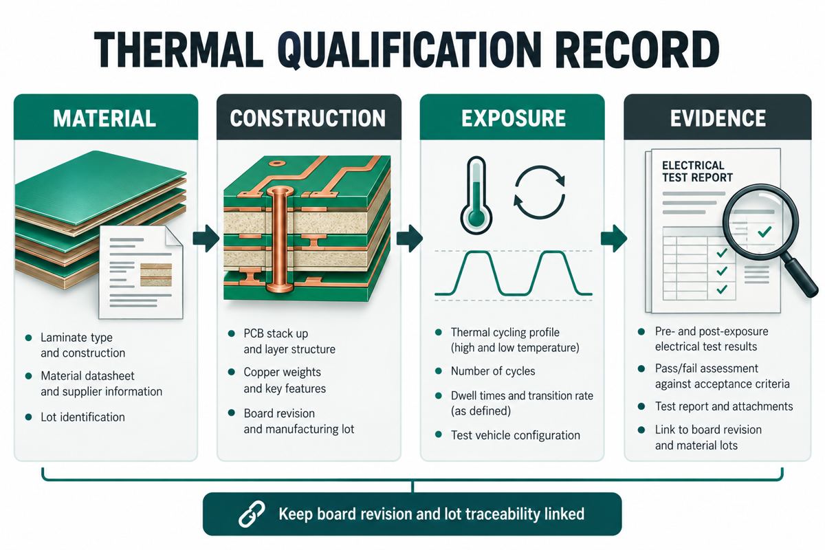
Use a plan that can distinguish a material hypothesis from an interconnect defect. Retain traceable samples and agree on the test conditions before interpreting an isolated failure.
- Define the exposure. List fabrication thermal history, planned assembly passes, expected rework and service temperature changes. A single oven peak does not describe the complete exposure.
- Define the construction. Record finished thickness, core and prepreg identities, via spans, stacked interfaces, hole dimensions and specified plating. Avoid changing several variables at once during a comparison.
- Measure before stressing. Identify the nets or representative test structures and the initial electrical measurement. Keep the instrument method consistent across samples.
- Apply the agreed thermal procedure. State conditioning, temperatures, dwell, ramp, number of cycles and when resistance is monitored. The procedure must match the engineering objective, not a convenient generic cycle count.
- Investigate the failed location. Correlate electrical changes with physical analysis. Use microsection evidence and its sampling limits rather than declaring every open a CTE failure.
- Close the corrective action. Recheck the affected construction and preserve the material, process and test revisions used for release.
Reddit discussions on microvia cracking and resistance changes after assembly illustrate why a passing initial electrical test may not settle a later reliability concern. They identify questions to investigate; they do not establish a universal failure mechanism or acceptance limit.
What Should You Put in a Laminate RFQ?
Send a controlled comparison sheet instead of asking only for “better FR4.” The following record can be copied into a technical enquiry and completed with the fabricator.
| Record | Provide or request | Release question |
|---|---|---|
| Material identity | Manufacturer, grade, core/prepreg construction and proposed alternatives | Is substitution subject to approval? |
| Expansion data | Both Z coefficients, total expansion, interval and methods | Are reference values distinguished from agreed limits? |
| Interconnect drawing | Board thickness, hole/via spans, interface arrangement and plating requirements | Does the qualification sample represent this structure? |
| Thermal history | Assembly profile, number of passes, rework allowance and service conditions | What exposure is actually covered? |
| Evidence plan | Electrical monitoring, physical analysis, sample quantity and lot traceability | Who approves the criteria and report? |
| Change control | Material, stackup or process changes that trigger review | When must qualification be repeated? |
For substitutions, ask the supplier to mark every changed field. “Equivalent Tg” is insufficient if expansion data, construction or the relevant test evidence differ. Conversely, do not reject an alternative solely because one headline figure differs: assess it against the actual design requirement.
PCB Z-Axis CTE FAQ
Is Tg the maximum operating temperature of a PCB?
No. Tg identifies a material transition, not a complete continuous-use rating. Establish the operating limit from the applicable material, product requirements and qualification evidence. Do not use the Tg figure as a universal temperature ceiling for every assembly made with that laminate.
Why are there two Z-axis CTE values?
The dimensional response changes around the glass transition. Suppliers therefore commonly report lower- and higher-temperature coefficients. Preserve their temperature regions and test methods when comparing data; averaging the two without accounting for the exposure interval can give a misleading result.
Why can a high-Tg board still have cracked vias?
Tg alone does not describe expansion or interconnect quality. Review material data, construction, interfaces and thermal history together. Local physical evidence is needed to identify the cause; a high-Tg label does not rule out a fabrication defect or a structure-dependent weakness.
Is 2.8% total expansion the same as 28 ppm/°C?
No. Percent total expansion is an accumulated change over a specified interval; ppm/°C is a rate. Converting the former to an average rate requires the temperature interval, and that average still does not describe separate below- and above-Tg behavior.
Does a thinner PCB always solve via cracking?
No. Reducing thickness reduces free dimensional change under otherwise identical assumptions, but the complete design may change at the same time. Hole geometry, copper quality, interfaces and qualification conditions still matter. Review the new stackup rather than treating thickness reduction as a guaranteed correction.
Should stacked microvias always be replaced with staggered vias?
Not as a blanket rule. Their reliability depends on the qualified construction and manufacturing process, while routing space and cost also constrain the choice. Ask for evidence representative of the proposed interface structure rather than applying a forum anecdote to every board.
Can a room-temperature electrical test prove thermal reliability?
It proves only the conditions covered by that measurement. A latent or intermittent connection may require thermal exposure and appropriately timed monitoring to reveal it. Define the test objective and acceptance criteria before deciding whether an initial continuity result is sufficient.
What must be checked before accepting an equivalent laminate?
Compare the identified grade and construction, relevant thermal data with matching methods, electrical requirements and existing qualification coverage. Record the approved substitution. If the supplier cannot show how it meets the controlled requirements, keep the substitution open rather than accepting it on Tg alone.
Need a Stackup and Material Review?
Send PCBtry your fabrication files, proposed stackup, via structure, quantities and expected thermal exposure through the contact page or email sales@pcbtry.com. Include the material grades under consideration and the evidence required for approval. Ask the team to confirm available constructions, any proposed substitutions and the scope of testing before you place an order.



0 Comments