




Solder paste powder size should be selected against the smallest stencil aperture, not component pitch alone. Type 4 has smaller particles than Type 3, but changing the type does not automatically fix bridging or incomplete deposits. Check aperture width, stencil thickness, paste formulation and measured printing results together before approving a change.
What does solder paste powder size mean?
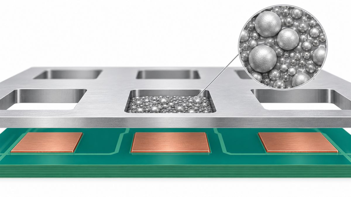
Paste contains metal powder suspended in a flux vehicle. The powder type describes a particle-size classification. It does not identify the alloy, flux chemistry, metal loading or suitability for a particular dispensing machine. A purchase description that says only “Type 4” is therefore incomplete.
Keep three identifiers separate: alloy tells you which metals form the joint; product formulation identifies the flux system and handling requirements; powder type describes particle size. Two Type 4 products can behave differently during printing. A change of both brand and type cannot isolate the effect of particle size.
Type 3 vs Type 4 vs Type 5: which should you evaluate?
The bands below describe the main particle-size range, not a promise that every particle has exactly those limits. Request the supplier’s applicable specification and lot documentation when distribution limits matter. A larger type number means finer powder.
| Powder type | Main size band | Reason to evaluate it | What still needs proof |
|---|---|---|---|
| Type 3 | 25-45 micrometers | Existing process already produces repeatable deposits through its smallest openings. | That the smallest revised aperture still releases enough paste. |
| Type 4 | 20-38 micrometers | A smaller opening makes the coarser powder a questionable starting point. | Transfer consistency, separation between deposits and finished joints. |
| Type 5 | 15-25 micrometers | Fine-feature printing remains difficult after geometry and process review. | That the complete formulation and handling window work, not just the smaller particles. |
The size bands are listed in Indium’s powder and stencil application note. FCT’s technical explanation describes the tradeoff: finer powder can help small-feature printing, while its greater surface area makes formulation and oxidation control important. Do not turn this into a universal shelf-life ranking; use the actual product data sheet.
How do aperture width and stencil thickness affect the choice?
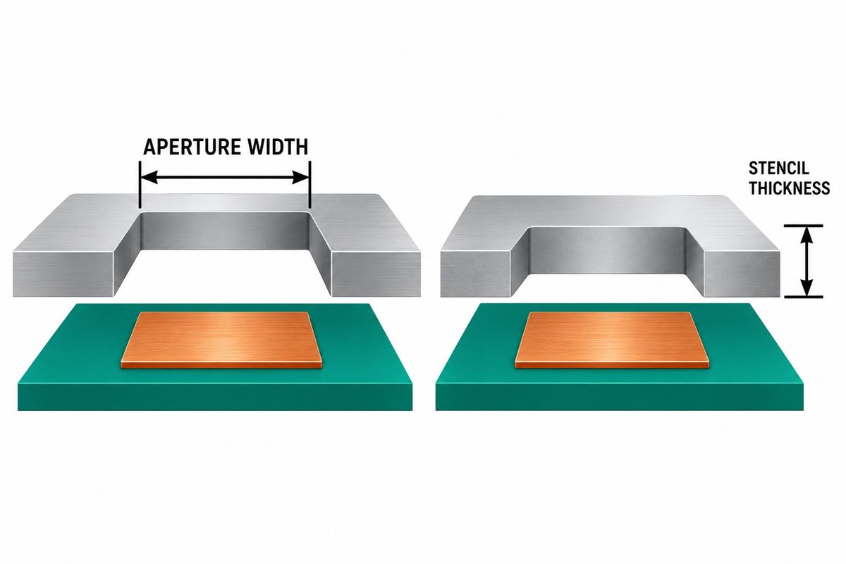
Read the paste-mask opening, not just the copper-pad size. Indium describes a five-particle screening rule for rectangular openings and different guidance for square or circular openings. Its five-ball discussion explicitly treats this as a heuristic, not a physical law. Do not apply the rectangular rule unchanged to BGA circles.
A second check is area ratio: opening area divided by aperture-wall area. For a rectangular opening, AR = L x W / [2 x t x (L + W)], with all dimensions in the same units. The application note uses 0.66 as a conventional guideline; passing it is not a production acceptance test.
Worked example, not a measured process: consider a 0.21 x 0.50 mm rectangular opening. Dividing its width by the upper main-band diameter gives 0.21/0.045 = 4.67 for Type 3 and 0.21/0.038 = 5.53 for Type 4. This makes Type 4 a reasonable trial candidate, not an approved recipe.
At 0.12 mm stencil thickness, the same opening has AR = 0.105/0.1704 = 0.616. At 0.10 mm, AR becomes 0.739. Thinning the stencil also reduces nominal aperture volume from 0.0126 to 0.0105 cubic millimeters, a 16.7% reduction. Better release geometry can therefore coexist with less available paste. Check joints needing more solder before thinning an entire stencil.
Which Kester NP505-HR parameters should you check?
This is a traceable product example, not a claim that PCBtry stocks or uses it. The Kester product page identifies the Type 4 jar below. Confirm the ordering code and current lot documentation before substitution.
| Parameter | Published value or condition | How to use it |
|---|---|---|
| Product / part number | NP505-HR / 7040211410 | Specify the complete code, not only T4. |
| Alloy | SAC305: Sn96.5Ag3Cu0.5 | Keep alloy changes separate from powder trials. |
| Powder / packaging | Type 4 / 500 g jar | Check the label against the purchase order. |
| Listed metal content | 88.5% | Do not treat this as the deposited volume fraction. |
| Optimal printing environment | 21-25 degrees C; 35-65% RH | Record actual conditions during evaluation. |
| Refrigerated shelf life | T3/T4: 12 months from manufacture at 0-10 degrees C | Check date and storage history; this is not open-stencil life. |
The environmental and storage conditions come from the NP505-HR technical data sheet, which also requires room-temperature stabilization before use. These are product-specific recommendations, not universal acceptance limits or guaranteed yields. No tolerance for the listed metal percentage is inferred here; obtain the supplier specification if it is contractual. For broader handling checks, see solder paste storage.
Why can finer solder paste still cause bridging?
First identify when separate deposits become connected. If the print is merged immediately after stencil lift, inspect registration, underside contamination, board support and aperture design. If deposits begin separate and spread during waiting or heating, investigate paste condition and slump. If bridging appears only after placement or reflow, compare placement displacement, solder quantity and thermal behavior.
A Reddit discussion about changing Type 3 to Type 4 illustrates the attribution problem: the product also changed. That is a useful question to investigate, not evidence that Type 4 inherently bridges more. Photograph the same locations after printing, after placement and after reflow so a powder change does not conceal a mechanical problem.
Use a slump investigation for time-dependent spreading and a separate reflow-process review for thermal issues. Do not repair every symptom by shrinking copper pads; the component land-pattern requirements still apply.
How should you qualify a change in powder type?
- Freeze the baseline. Record board and stencil revisions, exact paste code, lot age, conditioning, environment and printer settings. Identify the smallest apertures and the joints with the largest solder demand.
- State the reason for the change. Examples are intermittent missing deposits or a newly reduced opening. A vague goal such as “better paste” cannot define success.
- Control the comparison. Keep alloy and product family consistent where available. If the supplier changes flux formulation with powder type, record that fact: you are evaluating two products, not a pure particle-size experiment.
- Inspect repeated prints. Include startup and restart after a realistic pause. Record deposit volume, height, area and variation with SPI when available; photographs alone cannot establish volume capability.
- Inspect completed assemblies. Printing improvements must not introduce opens, bridges or other unacceptable joints. Define inspection coverage and acceptance criteria with the responsible engineer before the trial.
- Approve the documented combination. Release the paste, stencil and process revision together. A favorable single print is not evidence of sustained process capability.
For a prototype without SPI, keep labeled images and electrical/visual inspection results, and disclose the measurement limitation. Do not convert a visually good prototype into a numerical yield claim.
What should you send an assembler for a paste-selection review?
Save this table with the assembly release package. It makes the decision reviewable when a paste supplier, component footprint or stencil changes.
| Review item | Evidence to provide | Hold the decision when… |
|---|---|---|
| Critical opening | Paste-layer drawing with width, length, shape and reference designator | Only component pitch or copper-pad dimensions are known. |
| Stencil geometry | Thickness, local steps, revision and relevant fabrication notes | A thickness change has not been checked against larger joints. |
| Paste identity | Manufacturer, complete code, alloy, powder type, lot and data sheet | The proposed substitute is described only as T4 or T5. |
| Failure stage | Matched photos or measurements before placement and after reflow | All defects are attributed to powder without locating their onset. |
| Release evidence | Repeated-print results, assembly inspection and agreed criteria | Only one attractive print or an unsupported yield estimate is available. |
For a PCB assembly review, provide Gerber or supported fabrication data, BOM, placement file and the critical component data sheets. Include an existing stencil drawing and defect images when available. Ask which paste/stencil combination the assembler proposes and what validation is included, rather than prescribing a powder type in isolation.
Frequently asked questions about solder powder selection
What is the main difference between Type 3 and Type 4?
Type 4 uses finer particles. It can be a candidate for smaller stencil openings, but the type does not specify flux chemistry or assure a better finished joint. Compare the complete products.
Does a 0.4 mm pitch connector automatically need Type 5?
No. Pitch alone omits the paste opening and thickness. The fine-pitch hand-assembly discussion raises this practical problem; use the component drawing and stencil proposal to decide what to trial.
Does a 0.1 mm stencil automatically mean Type 4?
No. Thickness is only one dimension. A wide opening and a narrow opening through the same foil have different release geometry. The thin-stencil community question is best resolved with actual aperture dimensions.
Will Type 5 eliminate solder bridges?
No. Registration, deposit quantity, spreading, placement and reflow still need checking. Locate the stage where the bridge begins before changing materials.
Is SAC305 the same specification as Type 4?
No. SAC305 names an alloy composition; Type 4 names a powder-size class. The purchasing specification needs both, plus the product formulation.
Should I print paste straight from the refrigerator to keep it stiff?
Follow the product’s conditioning instructions instead. For the NP505-HR example above, Kester requires stabilization at room temperature. Cold printing is not a substitute for investigating deposit spread.
Can one paste cover both small and large components?
Possibly, but qualify both extremes on the board. Solving the smallest aperture does not prove adequate solder volume for larger joints; a local stencil solution may need review.
What is the minimum useful information for an assembler?
Send the board and placement data, BOM, critical component drawings, smallest paste openings, stencil thickness and exact paste identity if already chosen. Add stage-labeled defect images for troubleshooting.
Need help reviewing a fine-pitch assembly package? Contact PCBtry with those files and identify the critical reference designators. Request a paste-and-stencil review and a proposed inspection plan before approving production.



0 Comments