




PCB potting thermal stress cannot be controlled by choosing the lowest coefficient of thermal expansion alone. A useful material review also considers stiffness over temperature, cure shrinkage, enclosure restraint and the actual temperature history of the filled assembly. The right next step is a documented material comparison and representative qualification trial, not an unverified change to the mixing ratio or oven setting.
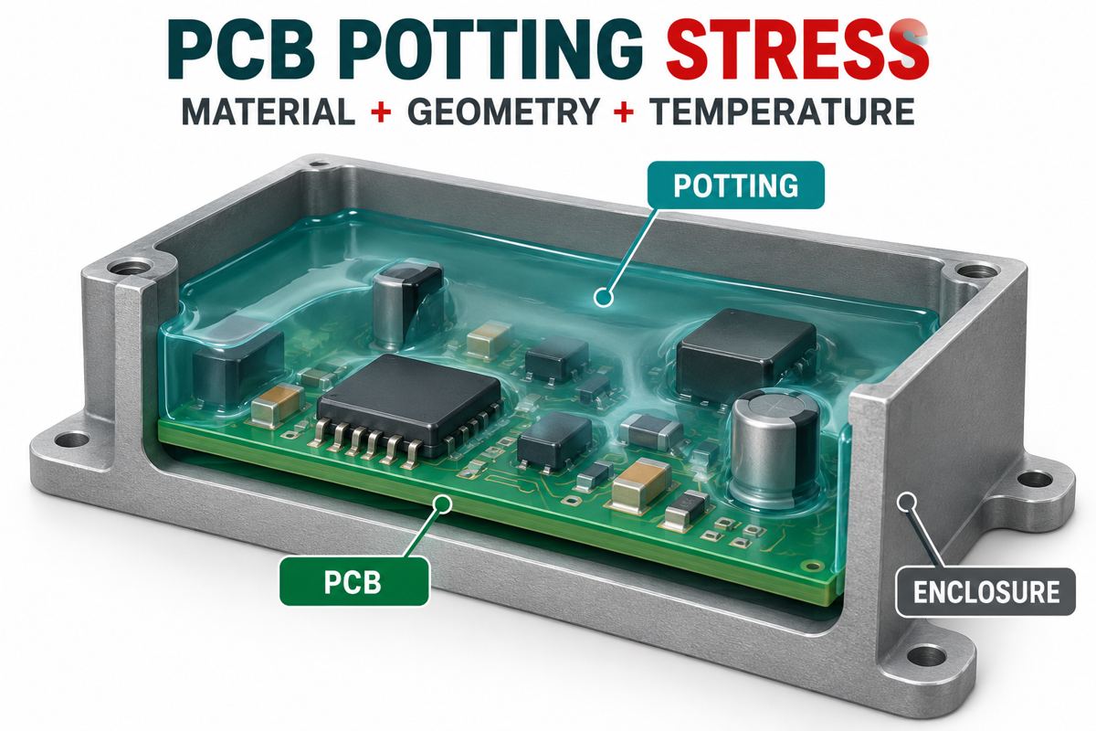
Why can potting damage PCB components?
A compound can protect an assembly environmentally while adding a mechanical load to its components. Separate the sources of that load before changing the process.
- Cure shrinkage: the material changes dimensions as it sets. Bonded surfaces can restrict that movement.
- Thermal mismatch: resin, component bodies, solder joints, board and enclosure do not necessarily expand together.
- Constraint: housing walls, mounting points and irregular resin thickness determine where movement is resisted.
These mechanisms can coexist with unrelated electrical faults. A failed post-potting functional test does not, by itself, identify a cracked capacitor or prove that the resin overheated. Preserve the failed unit, its pre-potting test result and the process record before destructive investigation.
A community discussion about broken components during encapsulation illustrates this diagnostic ambiguity: the initial question concerned reaction temperature, while replies also raised mechanical strain. That is a useful investigation prompt, not a verified root-cause report.
Why is a low CTE not enough?
CTE describes dimensional change with temperature; it does not state the force transferred into a component. A compliant material may accommodate movement that a more rigid material would resist. Adhesion and geometry also change the load path.
For a simplified free-expansion comparison, mismatch in length is approximately length × difference in CTE × temperature change, provided the coefficients are applicable over that temperature interval. Suppose two hypothetical materials differ by 50 ppm/K across a 20 mm length and a 60 K change. Their free-expansion difference is 0.060 mm. This is an illustrative calculation, not the movement or stress that a bonded board will actually experience.
Do not multiply that result by an arbitrary room-temperature modulus and call it a reliable joint-stress prediction. Real encapsulation involves three-dimensional constraints, temperature-dependent properties and time-dependent relaxation. If a temperature range crosses a glass transition, a single CTE value is particularly misleading.
Ask for modulus versus temperature and the test method where stress sensitivity is important. Shore hardness is a screening property, not a substitute for those data. A material with an acceptable service-temperature range is not automatically mechanically compatible with every component throughout that range.
Rigid vs flexible epoxy: which should you evaluate?
Compare formulations against the required function, rather than assuming every epoxy is hard or every soft compound is suitable. MG Chemicals describes 832FXT as a low-modulus, flexible epoxy for delicate circuitry and thermal cycling. That is a specific formulation characteristic, not a universal claim about epoxies.
| Decision | Rigid formulation | Flexible formulation | Evidence needed |
|---|---|---|---|
| Movement around delicate parts | Investigate strain transferred through bonded interfaces | Evaluate ability to accommodate movement | Properties over the actual temperature range; component-level results |
| Mechanical restraint | May support a rigid encapsulated structure | May allow more displacement | Shock, vibration and mounting requirements |
| Heat path | Do not infer conductivity from rigidity | Do not infer cooling from flexibility | Conductivity, geometry, interface and powered thermal test |
| Environment and repair | Review chemical exposure and removal consequences | Review adhesion, permeability and removal consequences | Product-specific compatibility and service plan |
Neither column is an automatic winner. A soft material that moves under the required mechanical load, or a rigid material that overstresses a sensitive part, can both be unsuitable. Set the acceptance criteria before selecting a candidate.
What do MG Chemicals 832B and 832FXT specifications show?
The following manufacturer-reported values are from 832B TDS version 5.4, April 2026 and 832FXT TDS version 1.1, September 2025. These are comparison data, not PCBtry capabilities or guaranteed lot acceptance limits. The tables do not provide plus/minus tolerances for these entries.
| Property | 832B | 832FXT | Condition or method |
|---|---|---|---|
| Glass transition | 49 °C | 20 °C | ASTM E1545 |
| CTE below / above Tg | 79 / 196 ppm/°C | 124 / 295 ppm/°C | ASTM E831; use the applicable region |
| Hardness | 80 Shore D | 80 Shore A | ASTM D2240; different scales |
| Thermal conductivity | 0.3 W/(m·K) | 0.2 W/(m·K) | 25 °C; ASTM E1461 |
| Reported peak exotherm | 106 °C | 50 °C | 250 g sample in fixed container geometry |
| A:B ratio, volume / weight | 2:1 / 2.3:1 | 1:1 / 1.15:1 | Different measurement bases |
The two hardness numbers are not equivalent simply because both say 80. Similarly, the larger CTE of the flexible material does not establish that it causes greater component stress. Request the missing mechanical data and qualify the assembly. Do not treat the reported exotherm as a maximum permitted component temperature or a prediction for a different fill volume.
How do you check cure heat without guessing?
Measure representative assemblies under an approved trial plan. An oven display measures its control condition, not every location inside the encapsulant.
- Fix the candidate: record product, TDS revision, lot, approved ratio and initial material temperature. Do not alter ratio to reduce heat.
- Represent the real geometry: use the intended enclosure, fill depth, board position and batch quantity. A shallow test cup cannot qualify a deep housing.
- Instrument relevant locations: have the process engineer define embedded temperature measurement near the bulk resin and vulnerable regions. Check sensor placement does not materially change the trial.
- Compare against applicable limits: review component, housing and material constraints, including duration. Stop and investigate an unapproved excursion rather than accepting it because the resin eventually hardened.
- Retest after stabilization: compare function with the baseline and preserve traceable results for the next environmental stage.
Use professional facilities and the product SDS. A public discussion of 70 °C oven curing is not authorization to apply that temperature to your material. Infrared surface readings can complement a trial, but they do not establish hidden resin-core temperatures.
If the primary defect is trapped air rather than mechanical compatibility, use the separate potting bubble investigation guide. A bubble-free appearance does not establish thermal-cycle reliability.
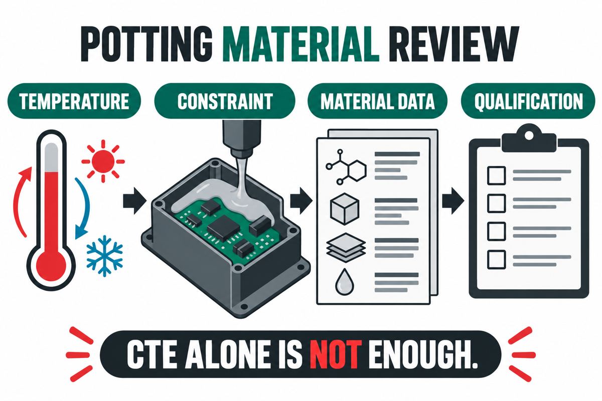
What belongs in a potting material qualification checklist?
Copy this matrix into the material-change review. Each row should have an evidence owner and a disposition, so an attractive datasheet number cannot silently replace a missing assembly test.
| Review item | Record for each candidate | Do not release while |
|---|---|---|
| Thermal environment | Minimum, maximum, dwell, ramps and powered states | The use profile is unspecified |
| Mechanical constraint | Mounts, enclosure interfaces, fill boundaries, delicate components | Trial geometry differs without justification |
| Material evidence | CTE regions, mechanical data, cure conditions and chemical compatibility | Critical properties or conditions are unknown |
| Cure trial | Actual temperature traces and pre/post function | Excursions or changed electrical behavior are unexplained |
| Environmental qualification | Approved test profile, sample plan and acceptance limits | Only a room-temperature visual check exists |
| Change control | Approved material revision, process window and requalification triggers | Substitutions can occur without review |
Sample count and cycling conditions must come from product requirements and a responsible qualification plan. There is no universal cycle count that certifies every potted PCB. Include functional monitoring appropriate to the failure of concern, because an intermittent connection may not be visible after the assembly returns to room temperature.
PCB potting thermal stress FAQ
Why does a PCB pass before potting but fail afterward?
Possible causes include temperature exposure, mechanical loading, contamination or an existing marginal connection. Classify the electrical symptom before selecting a mechanism. Compare traceable before-and-after data and investigate the failed region; do not assume every failure is an air void.
Can I cure any potting epoxy at 70 °C?
No. Use the specific material’s approved schedule and verify compatibility with the complete assembly. A temperature that accelerates one formulation may be inappropriate for another or for the housing and components involved.
Can a thermal camera measure the peak temperature inside the resin?
A surface image does not directly measure a hidden interior. Use a suitably designed instrumented trial when internal temperature matters. Treat surface measurements as supplementary evidence and document where every sensor actually measures.
Does the lowest CTE give the lowest component stress?
Not necessarily. Stiffness, adhesion, temperature range and geometry influence how differential movement loads components. Compare the complete material system rather than sorting candidates by one CTE value.
Are all epoxy potting compounds rigid?
No. Flexible epoxy formulations exist, including the manufacturer example discussed above. Check the actual grade and its mechanical behavior rather than relying on the chemistry name or an informal description such as “rubbery.”
Are small potting blobs safe around 0402 components?
Small volume is not a blanket exemption. Blob shape, bonded area, component construction and temperature cycling still matter. A discussion specifically about 0402 parts shows why the geometry and environment must accompany this question.
Should I put silicone under a rigid epoxy?
Do not add an unqualified intermediate layer as a universal fix. It changes adhesion, cure compatibility, heat transfer and the mechanical interface. Have both material suppliers and the product engineer review the combination, then test the intended geometry.
Is a successful room-temperature test enough?
No, not when the requirement includes temperature cycling. It establishes only the measured condition. The qualification plan must address the intended environment and failure modes, with documented acceptance criteria and appropriate electrical checks.
Request a PCB assembly material review
Send your BOM, assembly drawing, enclosure section, fill boundaries, temperature profile and candidate resin TDS through PCBtry’s contact page. Identify stress-sensitive parts and the required pre/post-potting tests. Ask the team to confirm the available assembly scope, engineering review and any external material qualification needed before a quotation is finalized.
Include the comparison matrix with unknown fields clearly marked. A useful review identifies what evidence is still needed; it should not turn a material brochure into an unsupported reliability promise.



0 Comments