




What Does the PCB Desmear Process Remove?
The PCB desmear process removes resin residue left on drilled hole walls before those walls are metallized. Its job is to expose the copper connection areas and prepare the surrounding dielectric for the next process. Desmear does not plate the hole, repair a damaged drill hole, or prove that the finished connection will survive service.
Picture a hole passing through a stack of copper sheets separated by insulating resin and glass. Drilling exposes the edges of the copper sheets, but heat and friction can spread resin across them. A film of insulation between an inner-layer copper edge and the new plated barrel can interfere with the connection. A hole that looks open from above is therefore not necessarily ready for plating.
This is particularly relevant to multilayer PCB construction, where a plated hole must meet selected internal copper layers. Removing loose dust alone does not establish that those interfaces are clean.
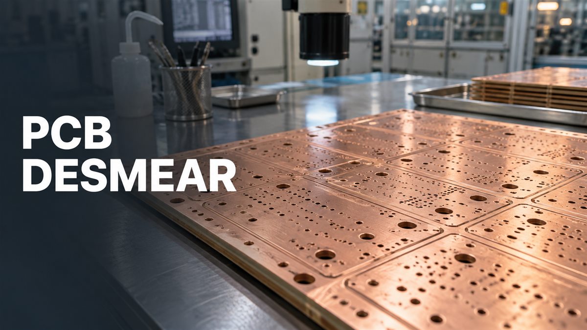
Desmear and etchback are related, but not identical. Desmear removes unwanted residue. Etchback deliberately recesses dielectric around an inner-layer copper edge to a specified geometry. More removal is not automatically better: the treatment must meet the board drawing and the qualified process.
Chemical or Plasma Desmear: Which Route Fits the Board?
Choose the route by the actual laminate grade, hole structure and demonstrated process results, not by assuming that plasma is always superior or that every FR-4 board takes the same chemical cycle.
| Route | What it does | What must be checked |
|---|---|---|
| Wet chemical desmear | A compatible conditioning and oxidation sequence removes resin, followed by neutralization and rinsing. | Material compatibility, bath condition, treatment exposure, hole access and removal of residues. |
| Plasma desmear | Reactive species in a controlled chamber treat organic residue and the exposed surface. | Gas recipe, power, pressure, loading, uniformity and compatibility with the complete material stack. |
| Combined treatment | Uses complementary stages when the qualified manufacturing route requires them. | Why each stage is needed, cumulative material removal, and evidence for the sequence as a whole. |
A vendor’s successful process for one laminate is a starting point for qualification, not a guarantee for another resin system. For example, Saturn describes a combined preparation route for its PTFE work. That is evidence of a specific manufacturer’s practice, not a requirement that every PTFE board use that exact sequence.
Both routes require industrial controls. Wet lines need appropriate chemical handling and waste treatment; plasma equipment needs suitable gas handling, exhaust and equipment safeguards. An EPA case study from 1996 illustrates the trade-offs, but its costs and operating conditions should not be treated as present-day specifications. This article is a process and purchasing guide, not a chemical mixing procedure.
How Does the PCB Desmear Process Work?
The practical sequence is to confirm the drilled structure, apply the qualified cleaning route, verify hole-wall condition and hand the panel into the correct metallization process. The following steps describe control points, not a universal recipe.
1. Confirm the material and drilling condition
Start with the released stackup, laminate grade, hole types and drilling records. Check for mechanical damage before trying to remove more resin. Torn glass or a badly formed hole may need a drilling-process correction; extra chemical exposure cannot reconstruct missing material. A buyer should identify approved material substitutions before production, because a substitute can change the preparation route.
2. Condition, remove residue and neutralize on a wet route
A common wet process uses a sweller to condition the resin, permanganate chemistry to remove it, and a neutralizer to clean remaining treatment residues. Rinsing separates the chemical stages. Technic’s desmear chemistry documentation describes these distinct functions. The products form a compatible system; individual steps should not be substituted casually.
The manufacturer controls exposure and chemistry against its qualified instructions. Too little treatment can leave residue; excessive treatment can remove more dielectric than intended. Useful evidence includes the approved process revision, relevant bath-control records and inspection of representative holes. A record that the conveyor ran is weaker evidence than a record showing the process remained within its operating limits.
3. Use the qualified plasma sequence where specified
For a plasma route, panels are processed in a controlled chamber. The manufacturer must account for the material stack and how the load presents the hole surfaces to the treatment. Do not translate one equipment supplier’s recipe directly to another chamber or load. The SCI Plasma process explanation provides the basic mechanism; production settings still require equipment- and product-specific validation.
4. Inspect and transfer to metallization
Use the agreed process checks to decide whether the panel can proceed. Keep identification and handling controls intact so a panel does not lose traceability between preparation and plating. An abnormal result calls for disposition by the responsible process engineer, not an automatic repeat cycle.
The downstream route matters. Some processes use electroless copper; others use direct metallization. Atotech lists both types of metallization technology. Desmear prepares the surface for that route but does not create the finished copper barrel itself.
How Do Material and Hole Geometry Change the Decision?
A change in material or hole geometry can invalidate an otherwise familiar process assumption. Review the changed input before carrying a previous job’s approval forward.
Example: the same drill diameter in a thicker board
Assume a mechanically drilled through hole is 0.30 mm in diameter. For this example, define drilled aspect ratio as the thickness drilled divided by the drill diameter, using millimetres for both:
- 1.60 mm thickness / 0.30 mm drill = approximately 5.3:1.
- 2.40 mm thickness / 0.30 mm drill = 8.0:1.
These are hypothetical geometries, not process limits. The second hole is longer relative to its opening, so the previous validation cannot be assumed to cover access, cleaning and subsequent metallization. The useful question is whether the qualified range includes the new geometry and load. Do not simply increase the treatment time.
State the diameter convention when comparing specifications. A finished plated hole is smaller than the drilled opening; an aspect ratio calculated from finished diameter will be different. For a blind via, use the relevant drilled depth, not automatically the total board thickness.
Example: replacing an epoxy grade with a hybrid stack
Suppose the drawing changes from an approved epoxy construction to a stack containing PTFE. The outer dimensions may remain identical, but the hole exposes different materials. The old recipe is therefore not approved merely because the hole size is unchanged. Request a review of the complete stack and the preparation/metallization combination.
A Shennan Circuits conference paper on PTFE-FR-4 blind-via construction illustrates why material combinations and resin-removal details matter. Its experimental sequence is not a general manufacturing instruction. For a new build, agree which representative coupons and qualification results are needed before release.
What Evidence Shows That Hole Preparation Worked?
No single photo or electrical pass report proves the entire process. Combine traceable process records with inspection of the relevant interfaces and any reliability tests required by the product specification.
| Evidence | Question it helps answer | What it does not prove |
|---|---|---|
| Process records tied to the lot | Was the approved route run under its controlled conditions? | That every individual hole is acceptable. |
| Representative microsections | What does the sampled hole wall, copper barrel and inner-layer interface look like? | That unsampled holes are identical, or that a poorly located cut reveals every defect. |
| Specified electrical test | Do the tested connections meet the electrical limits under the test conditions? | Copper adhesion or survival through future thermal exposure. |
| Required thermal/reliability evaluation | Does the sampled structure meet the agreed criteria after the stated stress? | Unlimited lifetime or performance under a different environment. |
A microsection is a prepared slice through the board that exposes features hidden inside a hole. Read the report in this order: lot and coupon identity, hole type, cut location, image scale, measured features, test condition and acceptance reference. A sharp image without those details is difficult to use for release.
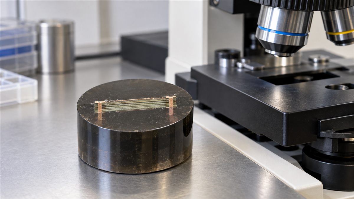
Consider a hypothetical supplier report containing only “electrical test: pass.” That may answer the electrical screening question, but it leaves the hole-wall and material-change questions unresolved. The next action is to request the missing evidence from the agreed plan, not to declare the lot defective without investigation.
What Should You Check When Plating Defects Appear?
Investigate the drilling, preparation and metallization sequence together. Similar visible defects can have different causes, so a plating void does not automatically diagnose insufficient desmear.
| Observation | Competing possibilities | Useful first evidence |
|---|---|---|
| Incomplete copper coverage | Residual contamination, inadequate activation, access or downstream plating problems. | Lot history, affected hole types, cross-sections and metallization records. |
| Excessive dielectric recession or damaged wall | Over-aggressive treatment, drilling damage, or interaction of both. | Drilling condition and preparation exposure, compared with qualified limits. |
| Open connection after thermal exposure | Weak interface, barrel defect, material/structure stress or another interconnect problem. | Failure location, pre/post-stress measurements and targeted sections. |
Michael Carano’s desmear defect guide specifically cautions that drilling can contribute to defects attributed to desmear, and that excessive treatment can also be harmful. Preserve an untreated failure sample, associated reports and lot identifiers before changing the process. Verify a corrective action under the conditions that originally exposed the problem.
What Should Be Agreed Before Production Release?
Agree on the board structure, acceptance basis and evidence package before fabrication. Buyers do not need to prescribe a proprietary chemistry recipe; they do need a clear definition of what the manufacturer is expected to build and demonstrate.
Use this short request as a starting point for your manufacturing discussion:
- Product identity: drawing revision, approved stackup, laminate grades and substitution restrictions.
- Hole definition: through/blind/buried structure, drill data, finished-hole requirements and plating requirements.
- Process applicability: confirmation that the proposed preparation and metallization route is qualified for this construction.
- Inspection plan: representative coupons or features, sampling, measurements and report traceability.
- Acceptance basis: drawing notes and applicable specification revision, with agreed defect criteria and required stress tests.
- Exceptions: who approves deviations, material changes and reprocessing, and what evidence is needed.
Keep the released Gerber and drill file package consistent with the drawing. If the request changes the laminate but not the filenames, clearly identify the revision so the factory does not qualify the wrong construction.
This checklist helps separate two decisions: “the requested process was performed” and “the supplied evidence supports acceptance.” A complete route record cannot substitute for a missing acceptance requirement, and an attractive micrograph cannot substitute for lot traceability.
PCB Desmear Questions
Can I desmear an assembled PCB to fix a connection?
No. Desmear belongs to controlled bare-board manufacturing before metallization. It is not a cleaning method for an assembled board or a field repair for a damaged plated hole. An existing connection fault needs diagnosis and an appropriate repair or replacement decision.
Does desmear add copper to the hole?
No. It prepares the exposed surface. Metallization and subsequent plating establish the conductive structure. A completed desmear operation alone does not establish copper coverage or finished plating thickness.
Is brown oxide treatment the same as desmear?
No. They serve different stages and surfaces. Inner-layer copper treatment supports bonding during multilayer construction; hole-wall desmear addresses residue after drilling. A manufacturing sequence may contain both without making them interchangeable.
Does a high-Tg label specify the desmear recipe?
No. Tg describes a material transition, not a complete chemical-compatibility specification. Identify the exact grade and construction. Two products carrying a similar Tg label can still require different manufacturing validation.
Can the factory repeat the cycle if a hole is not clean?
Only under an approved disposition or reprocessing procedure. Repetition adds exposure and may increase unwanted material removal. The responsible engineer should determine the cause and check the permitted treatment history before deciding what happens next.
Why request sections if electrical testing passed?
Electrical screening and structural inspection answer different questions. A conductive path at the test condition is not proof of interface quality or thermal durability. Request the evidence specified for the product rather than assuming either test replaces the other.
What temperature and time should I put on the drawing?
Do not copy generic settings from a blog. Unless your organization owns a validated process specification, define the material, structure, acceptance criteria and required evidence. The manufacturer and chemistry or equipment supplier determine suitable controlled settings.
Should desmear appear as a separate quotation line?
Not necessarily. It may be included in the fabrication route. What matters is that the quote covers the specified construction and agreed verification. Clarify any additional qualification, special coupons or reporting before comparing prices.
Preparing a new multilayer build? Send your stackup, laminate grade, Gerber and drill files, hole requirements and acceptance plan through PCBtry’s contact page. Request confirmation of the proposed manufacturing scope and inspection deliverables before approving production.



0 Comments