
Spot the wrong ballast in a fixture and you get flickering, overheating, or a board that simply refuses to strike the lamp. Get it right and the lighting system runs as the designer intended for years. A PCB ballast — the electronic circuit board that regulates current to a lamp — comes in dozens of shapes, ratings, and control schemes. This guide walks you through the exact methods technicians and procurement engineers use to nail down which ballast is on their bench, whether it needs replacing, and how to source the correct one without guesswork.
What a PCB Ballast Actually Is (and Why Identification Matters)
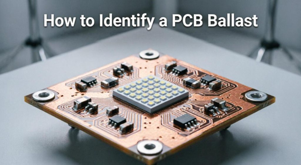
Strip away the housing of any modern fluorescent, LED, HID, or discharge-type fixture and you will find a printed circuit board populated with capacitors, inductors, a switching IC, MOSFETs, and a handful of passive components. That board is the electronic ballast. Its job: take raw mains voltage and sculpt it into precisely the current, voltage, and frequency the connected lamp demands.
Knowing which ballast you have becomes critical in several real situations. A maintenance tech troubleshooting a flickering office light needs to match the replacement to the original electrical spec. A procurement engineer evaluating a supplier quote must verify the ballast’s input voltage, output class, and certification marks against the fixture’s design requirements. And anyone ordering spare parts for a batch of industrial fixtures — whether 50 units or 5,000 — cannot afford to install a mismatched board. Wrong wattage rating alone can shorten lamp life by half or trigger a thermal shutdown.
Inside the Board: How a PCB Ballast Functions
Understanding the internal architecture helps you read the board more intelligently during inspection. Most electronic ballasts follow a similar signal path, though component choices vary widely between manufacturers and lamp types.
The incoming AC passes through an EMI filter — typically one or two common-mode chokes paired with X- and Y-class capacitors — to keep switching noise from polluting the power line. A bridge rectifier then turns the AC into DC, and a bulk electrolytic capacitor smooths the result. If the ballast carries an ENERGY STAR, EU ErP, or DLC listing, you will also find a power factor correction stage, either a boost-type active PFC or a simpler passive capacitor-inductor arrangement, pushing the power factor above 0.9.
From there, the real work happens in the high-frequency inverter. A half-bridge or full-bridge arrangement of MOSFETs (or IGBTs in higher-power HID designs) chops the DC bus at 20–60 kHz, feeding a resonant output tank built from discrete inductors and capacitors. This resonant circuit serves double duty: it generates the high ignition voltage needed to strike the lamp, then throttles back to regulate steady-state current once the arc is established. A dedicated controller IC — parts from Infineon, STMicroelectronics, Osram, or Texas Instruments are common — orchestrates the switching, monitors for fault conditions (open lamp, shorted output, over-temperature), and responds to dimming commands on dimmable variants.
When you examine a board up close, spotting the controller IC number (printed or laser-marked on the package) is one of the fastest ways to cross-reference the ballast’s specifications in a manufacturer datasheet.
The Main Categories: Which Type of PCB Ballast Do You Have?
Ballast boards are not interchangeable across lamp technologies. A fluorescent ballast cannot drive an LED panel, and an LED constant-current driver would destroy a metal-halide lamp. Recognizing the category first narrows your search dramatically.
Fluorescent electronic ballasts are the most familiar. Long, narrow boards sized to slide into linear tube fixtures (T8, T5, CFL), they use a half-bridge topology and a resonant output. Labels usually state lamp count and type directly — something like “1×T8 36W” or “2×T5 28W.”
LED driver ballasts are physically compact, often mounted on a metal plate that doubles as a heatsink. Their output is specified in constant current (milliamps) rather than lamp wattage — you will see markings like “700 mA / 42V DC.” Many include a PWM or 0–10V dimming input alongside the power conductors.
HID electronic ballasts for metal-halide, high-pressure sodium, and ceramic discharge lamps are noticeably bulkier. The output stage carries a separate ignitor or strike transformer capable of delivering 2–4 kV pulses. Board labels tend to state both the lamp wattage (150W, 250W, 400W) and lamp chemistry (MH, HPS, CDL).
Dimmable and smart ballasts — DALI, DMX, 0–10V, or even Bluetooth/Zigbee-equipped — add a microcontroller and a communication interface to the standard power stages. You will spot extra connector pads, an address label (for DALI-addressable units), or sometimes a small wireless module soldered near the control IC.
| Ballast Type | Typical Lamps | Board Shape | Key Label Clues |
|---|---|---|---|
| Fluorescent Electronic | T8, T5, CFL | Long, narrow rectangle | Lamp count and wattage (e.g., “2×T5 28W”) |
| LED Constant-Current | LED panels, downlights, street lights | Compact, often with metal base | Output in mA (e.g., “700 mA”) |
| HID Electronic | Metal halide, HPS, ceramic discharge | Bulk, large heatsinks and transformers | Lamp wattage and chemistry (e.g., “400W MH”) |
| Dimmable / Smart | Architectural, IoT-connected, DALI systems | Varies; extra connectors and MCU visible | DALI address, dimming protocol markings |
Visual Inspection: Reading the Board Without a Meter
Before reaching for any test equipment, a careful look at the board itself usually tells you most of what you need to know. Here is how experienced technicians approach it.
Start With the Label Block
Nearly every production ballast carries a printed or silk-screened identification area somewhere on the board. It will list the manufacturer (or at least a logo), a model or part number, the input voltage range, the output rating (wattage, current, or both), lamp compatibility, and regulatory marks — UL, ETL, CE, CCC, and so on. In many cases this label gives you enough to look up a direct replacement without further testing. If the label is missing or illegible — common on older fixtures — move to the next steps.
Use Board Dimensions as a Quick Filter
The physical footprint is surprisingly informative. Fluorescent ballast boards run 200–300 mm long but only 25–35 mm wide, matching the narrow channel inside a tube fixture. LED driver boards are compact, frequently under 100 × 60 mm. HID boards are unmistakable: heavier, with iron-core transformers and aluminum heatsinks that can triple the weight compared to a fluorescent equivalent.
Spot the Telltale Component Groups
Once you know the general shape, certain component clusters confirm the type. A large ferrite-core toroid sitting near the output end almost certainly marks a fluorescent resonant ballast — that is the output inductor. An LED board, by contrast, will show a current-sense resistor (a low-value, high-wattage part, often in the range of 0.1–1 Ω) right next to the output terminals. HID boards give themselves away with a bulky strike transformer or a separate ignitor module wired in series with the output. Smart ballasts are identifiable by the presence of a small MCU package (typically a QFP or SOIC with many pins), additional header pads for DALI or 0–10V signals, and sometimes a small daughter board for wireless connectivity.
Don’t Overlook the Silkscreen
PCB silkscreen text — the white printing on the board surface — often includes the designer’s internal project code, the PCB revision number, and pin-function labels at each connector. These markings can be surprisingly useful for matching a replacement board to the original wiring harness, especially on fixtures from OEMs that rebrand ballasts from third-party manufacturers.
Electrical Testing: Confirming What the Eyes Can’t See
Visual clues get you 80% of the way there. The remaining 20% — particularly when a label is missing or you need to verify a board’s condition before committing to installation — calls for a few standard electrical checks.
Input Voltage Verification
With the fixture disconnected from mains power, set a digital multimeter to AC voltage and measure across the ballast’s input terminals. A ballast rated for universal input (100–277V AC) will measure near zero in a powered-down state, so this test is really about confirming wiring continuity from the line connector to the input filter stage. If you suspect a blown input fuse, switch to continuity mode and check across the fuse holder.
Continuity and Resistance Checks
On a healthy fluorescent ballast, measuring resistance between the two output lamp terminals should show a low but non-zero reading — typically a few ohms through the output inductor. An open circuit (infinite resistance) points to a burned winding or a failed output capacitor. LED driver boards behave differently: measuring across the constant-current output with no load will show the full open-circuit voltage the driver attempts to maintain (often 40–60V), which is normal and does not indicate a fault.
Capacitor Health
The bulk electrolytic capacitor on the DC bus is one of the most failure-prone components on any ballast. A visually bulging or leaking cap is an immediate red flag. For a more quantitative check, discharge the capacitor safely through a bleeder resistor, remove it from the board (or at least disconnect one leg), and test it with an ESR meter. A healthy 100 µF / 400V electrolytic at room temperature should read well under 1 Ω equivalent series resistance. Values climbing above 5 Ω suggest the cap is drying out and the ballast will exhibit symptoms such as dim starting, flickering under load, or outright failure to strike.
MOSFET and Diode Checks
Switching MOSFETs in the inverter stage are another common failure point, especially in fixtures exposed to frequent on/off cycling or voltage transients. With power off and capacitors discharged, use the diode-test function on your multimeter to check each MOSFET’s drain-to-source junction. You should see a forward-biased body diode in one direction and an open circuit in the other. A short in both directions means the part is destroyed; an open in both directions suggests a bond-wire failure. Either way, the board needs component-level repair or full replacement.
Decoding the Label: What Every Marking Tells You
A ballast label is essentially a condensed datasheet. Here is how to read the most common fields you will encounter.
Manufacturer and Logo: Recognized names include Philips Advance, Osram/Tridonic, Universal Lighting Technologies, BOKE, Eaglerise, and Philips (now Signify). Private-label or OEM boards will carry a less familiar brand but often share the same PCB layout as a well-known equivalent — cross-referencing the controller IC number can confirm compatibility.
Model Number: This is your fastest path to a replacement. Enter the exact model number into a distributor search (Mouser, Digi-Key, Farnell) or the manufacturer’s own catalog portal. If the part is discontinued, the cross-reference databases at sites like Octopart or Aging-Components can point to a drop-in successor.
Input Ratings: “120–277V AC, 50/60 Hz” means the ballast works on both North American and European mains (and most other regions). A label reading only “120V AC” indicates a single-voltage design that will fail or perform poorly on 230V systems.
Output Ratings: For fluorescent and HID ballasts, this is stated as wattage and sometimes current: “32W T8” or “150W MH.” For LED drivers, expect current and voltage: “1050 mA, 22–42V DC.” The wattage range tells you the maximum load the ballast is designed to handle — connecting a higher-wattage lamp risks overheating the output stage.
Certification Marks: UL (North America), CE (European Economic Area), CCC (China), SAA (Australia), and RoHS compliance each confirm that the ballast has passed a specific set of safety and environmental tests. These marks are not optional decorations; they are legally required in most markets. A board lacking the appropriate regional certification cannot be legally installed in commercial buildings in that jurisdiction.
Date Code and Batch Number: Often printed in a small dot-matrix or inkjet block near the board edge. Useful for tracking warranty claims and identifying production runs that may have been affected by a known component defect.
Materials and Build Quality: What Separates a Good Ballast From a Cheap One
Not all PCB ballast boards are created equal, and material choice tells you a lot about expected lifespan and reliability.
The board substrate itself is typically FR-4 (glass-reinforced epoxy laminate), rated for a glass transition temperature around 130–140 °C. Higher-end HID and industrial ballasts may use FR-4 with a higher Tg (150–170 °C) or even ceramic substrates for extreme thermal environments. LED driver boards in outdoor or high-bay applications sometimes use aluminum-core PCBs (metal-core PCB, or MCPCB) that conduct heat away from power components far more effectively than standard FR-4.
Passive component quality varies dramatically between budget and premium boards. A well-made ballast uses 105 °C–rated electrolytic capacors from reputable brands (Nichicon, Panasonic, Rubycon, United Chemi-Con) with rated lifetimes of 5,000–10,000 hours at full temperature. Budget boards may substitute 85 °C parts with 2,000-hour ratings — a difference that shows up as premature failure within 18–24 months of continuous operation. Transformer bobbins, ferrite core grades, and even PCB copper weight (1 oz vs. 2 oz) all contribute to the board’s ability to handle sustained thermal stress.
On the manufacturing side, look for clean solder fillets, consistent component alignment, and clear conformal coating on boards destined for humid or dusty environments. These are hallmarks of an ISO 9001–certified production line with proper AOI (automated optical inspection) and in-circuit testing at end-of-line.
Industry Applications: Where PCB Ballasts Show Up
PCB ballasts are not limited to office tube lights. They appear across a surprisingly wide range of industries and applications, each imposing its own constraints on the board design.
In commercial and institutional buildings — offices, schools, hospitals, retail — fluorescent and LED ballasts account for the largest installed base. These fixtures run 12–18 hours a day, and reliability expectations are high; a failed ballast in a hospital corridor is not just inconvenient, it is a safety issue. Procurement in this sector prioritizes long-rated-life components, UL or ETL listings, and compatibility with existing dimming infrastructure (often 0–10V or DALI).
Industrial facilities use ballasts in high-bay lighting, machine-tool task lights, and cleanroom fixtures. Here, ambient temperatures can exceed 50 °C, vibration is constant, and electromagnetic interference from variable-frequency drives is a constant companion. Industrial-spec ballasts typically carry wider operating temperature ratings (–20 °C to +50 °C or higher), conformal-coated boards, and input filtering rated for noisy power environments.
Outdoor and street lighting presents perhaps the toughest challenge. LED driver ballasts in street-light housings face direct temperature swings from –40 °C to +60 °C, moisture ingress, and salt spray in coastal areas. IP66 or IP67-rated enclosures are standard, but the board inside still needs to withstand thermal cycling that cracks solder joints on poorly designed assemblies. This is where MCPCB substrates and high-quality potting compounds earn their keep.
HID ballasts remain prevalent in sports venues, parking structures, and industrial high-bay applications where extremely high lumen output is required. Their boards are built to handle the thermal load of 250–1000W lamps and the voltage spikes generated during lamp ignition cycles.
Specialty applications include horticultural lighting (LED grow-light drivers with tunable spectrum outputs), UV curing systems (high-power ballasts driving medium-pressure UV lamps), and marine/aviation lighting where vibration resistance and extreme reliability are non-negotiable.
How to Compare Replacement Ballasts Without Guesswork
When the original ballast is unavailable or you are evaluating alternatives from different suppliers, a structured comparison prevents costly mistakes.
Electrical compatibility comes first. Input voltage range, output current or wattage, and lamp type must match the fixture exactly. A ballast rated for one 32W T8 cannot drive two 32W T8 tubes — the output current capacity is different, and the lamp-detection circuit on some models may not recognize the second lamp. For LED drivers, the output current must match the LED module’s forward current specification within ±5%. Too much current causes overheating and shortened LED life; too little means dim output and possible flicker at low levels.
Physical fit is the second gate. Measure the original ballast’s length, width, and mounting-hole spacing before searching for a replacement. Even small differences — 2–3 mm in mounting-hole pitch — can turn a straightforward swap into a fabrication project. Connector type and pinout must also match. Some manufacturers use proprietary plug connectors; if the replacement has screw terminals instead, you will need to verify that the wiring harness can be adapted safely.
Dimming protocol alignment matters more than people realize. A 0–10V–dimmable ballast connected to a DALI control system will not respond to dimming commands — it will simply run at full output. Conversely, a non-dimmable ballast connected to a dimmer circuit may exhibit erratic behavior or early failure. Always confirm that the ballast’s dimming interface matches the installed control system.
Efficiency and power factor ratings affect operating cost and regulatory compliance. A ballast with 0.92 power factor and 90% efficiency will waste noticeably less energy than one rated at 0.85 PF / 85% efficiency — a difference that adds up quickly across hundreds of fixtures in a commercial building.
Lifespan and warranty terms round out the comparison. Premium manufacturers typically rate their electronic ballasts at 50,000+ hours (for LED drivers) or 40,000+ hours (for fluorescent ballasts) and back the rating with a 5-year warranty. Budget alternatives may quote similar numbers but offer only a 1–2 year warranty — a hint about the manufacturer’s own confidence in the product.
Real-World Application Cases
Case 1: Office Retrofit — Fluorescent to LED
A 200-unit office building in Chicago replaced aging T8 fluorescent fixtures with LED tube retrofits. The original Philips Advance ballasts (model A232T8IS269K) were magnetic, 20+ years old, and drawing excessive standby power. The new LED tubes required ballast-compatible (Type A) or ballast-bypass (Type C) configurations. The facilities team identified each ballast by its label, confirmed the wiring topology, and chose Type C external LED drivers for maximum energy savings. Result: 42% reduction in lighting energy consumption, with no changes to the existing fixture housings.
Case 2: Warehouse HID-to-LED Conversion
A logistics warehouse in Shenzhen operating 600W metal-halide high-bay fixtures needed a lighting upgrade for both energy savings and improved light quality for barcode scanning. The existing HID ballasts (marked “MH 600W, 400V output”) were identified through label reading and confirmed by measuring the output strike voltage with an HV probe. The replacement 200W LED high-bay drivers were sourced with matching dimming interfaces (0–10V) to integrate with the building’s existing daylight-harvesting system. The new ballasts’ PFC stage met local utility rebate requirements, recovering roughly 30% of the project cost.
Case 3: Flickering Office Lights — Root Cause Found at the Board Level
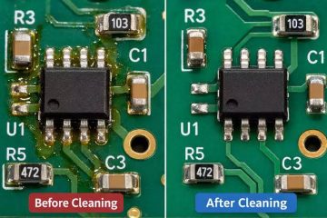
In a Dallas law office, a bank of six T5 fixtures developed intermittent flickering after a summer power surge. A visual inspection revealed no label damage, but the ESR test on the bulk electrolytic capacitor in each ballast showed values between 8 and 15 Ω — far above the healthy sub-1 Ω range. Replacing the capacitors (100 µF / 450V, 105 °C Nichicon parts) on all six boards restored normal operation at a component cost of roughly $4 per board, versus $35–50 for complete replacement ballasts.
Common Pitfalls and How to Avoid Them
Even experienced technicians run into trouble when identifying or replacing PCB ballasts. Here are the most frequent mistakes we see — and how to sidestep each one.
Mistake 1: Assuming wattage alone determines compatibility. A 32W fluorescent ballast and a 32W LED driver are completely different devices. They operate at different voltages, deliver current in different ways, and use incompatible lamp interfaces. Always verify the lamp technology, not just the wattage.
Mistake 2: Ignoring power factor requirements. In many jurisdictions, commercial buildings must maintain an aggregate power factor above 0.9. Installing ballasts with passive-only PFC (power factor around 0.6–0.7) can push the building out of compliance and trigger utility penalties. Check the PF rating on the label before purchasing.
Mistake 3: Overlooking temperature ratings in outdoor applications. A ballast rated for 0–40 °C will fail prematurely if installed in an unventilated outdoor fixture exposed to direct sunlight. For outdoor or high-bay use, insist on a ballast rated to at least 50 °C ambient, and verify that the electrolytic capacitors on the board carry matching or higher temperature ratings.
Mistake 4: Buying unmarked or counterfeit boards from unverified sources. No-label ballasts from unauthorized sellers may lack proper EMI filtering, carry underrated components, or fail to meet the safety certifications they claim. The short-term savings disappear quickly when the board fails in warranty or causes a fixture-level fire. Source from established manufacturers or authorized distributors, and insist on seeing test reports if the price seems unusually low.
Mistake 5: Forgetting about dimming compatibility. Installing a non-dimmable ballast on a circuit controlled by a dimmer switch causes erratic output and accelerates component wear. Always match the ballast’s dimming capability to the installed control system.
How to Choose a Reliable PCB Ballast Supplier
Finding the right ballast is half the job. Finding a supplier who can deliver consistently — with proper documentation and responsive support — is the other half.
Certifications should be your first filter. A supplier offering UL-listed, CE-marked, and RoHS-compliant ballasts demonstrates investment in product safety and regulatory compliance. For specialty applications (medical facilities, automotive, military), verify that the supplier holds the relevant industry-specific certifications: ISO 13485 for medical environments, IATF 16949 for automotive, or MIL-STD compliance for defense applications.
Manufacturing capability matters for volume orders. A supplier with SMT assembly lines, automated optical inspection (AOI), in-circuit testing (ICT), and end-of functional testing can deliver consistent quality at scale. Ask about their defect rates (a well-run line targets below 50 DPPM — defects per million parts) and whether they offer incoming inspection support for your quality team.
Customization options add long-term value. If your fixture design requires a non-standard board shape, specific connector type, or modified dimming behavior, a supplier with in-house PCB design and prototyping capability can develop a purpose-built ballast more quickly and cost-effectively than retrofitting an off-the-shelf part.
Supply chain transparency protects you from surprises. Ask for the component bill of materials (BOM), lead-time commitments, and last-time-buy notices. A supplier who proactively communicates when a critical IC is going end-of-life — and offers an approved alternative — is far more valuable than one who simply stops shipping when inventory runs out.
Buying Checklist: What to Verify Before Placing an Order
Run through this list before committing to a purchase, whether the order is for 10 prototypes or 10,000 production units:
- Confirm input voltage range matches your target market (120V, 277V, or universal 100–277V).
- Verify output current/wattage and lamp compatibility against the fixture design specification.
- Check that dimming protocol (0–10V, DALI, PWM, or none) matches your control system.
- Ensure physical dimensions and mounting-hole positions fit the fixture housing without modification.
- Confirm the board carries all required safety certifications for your installation jurisdiction.
- Request and review the manufacturer’s datasheet, test report, and reliability data.
- Verify the electrolytic capacitor temperature rating and expected lifespan meet your application’s duty cycle.
- Ask for a production sample and run it through your own fixture-level validation before approving a bulk order.
- Clarify warranty terms, defect resolution process, and lead-time guarantees.
- For outdoor or harsh-environment applications, confirm conformal coating and IP rating of the assembled ballast.
Frequently Asked Questions About PCB Ballast Identification
Can I use a multimeter to tell if a PCB ballast is electronic or magnetic?
Yes, with the fixture powered off. Disconnect the ballast and measure resistance across its input terminals. A magnetic ballast will show very low resistance (a few ohms or less) through its iron-core winding. An electronic ballast will show a higher, more complex resistance reading because the input filter stage and rectifier circuit are in the path. Some digital multimeters also offer an inductance measurement mode — a magnetic ballast will read in the millihenry range, while an electronic ballast’s input inductance is much lower.
What does it mean if my ballast label says “Class P”?
A Class P ballast includes built-in thermal protection — a thermostat or thermally sensitive fuse that disconnects power if the ballast’s internal temperature exceeds a safe threshold. This is a UL safety requirement for ballasts installed in enclosed fixtures where heat buildup is a concern. If you are replacing a Class P ballast, the replacement should also carry the Class P rating to maintain the same level of thermal protection.
Is it safe to test a ballast while the fixture is powered on?
Testing a live ballast is possible but requires appropriate safety precautions and equipment. Input voltage measurements with a rated CAT III or CAT IV multimeter are generally safe when performed by qualified personnel. However, output-stage measurements on HID ballasts involve voltages that can exceed 1,000V during lamp strike, and should only be performed with proper HV-rated probes and isolation techniques. When in doubt, perform all identification and testing with power disconnected.
How do I cross-reference a discontinued ballast model?
Start with the manufacturer’s own cross-reference tool — most major brands (Philips Advance, Osram/Tridonic, Universal) maintain online databases. If the manufacturer no longer supports the product, third-party platforms like Octopart, Mouser Cross-Reference, or Aging-Components can suggest equivalent models from other brands. The key parameters to match are input voltage, output current, lamp type compatibility, and physical mounting dimensions.
Why does my new ballast hum louder than the old one?
A faint hum (below 25 dB at 1 meter) is normal for electronic ballasts and comes from magnetostriction in the inductors and transformers. Louder buzzing usually indicates a loose core lamination, a cracked potting compound, or operation at a switching frequency near the audible range (below 20 kHz). Low-quality ferrite materials can also produce more audible noise. If the hum is intrusive, check whether the ballast’s mounting hardware is tight — a loose ballast vibrates against the fixture housing and amplifies the sound.
Can I replace a magnetic ballast with any electronic ballast of the same wattage?
Not necessarily. While wattage must match, electronic ballasts also differ in lamp-start method (instant-start, rapid-start, program-start), wiring topology, and dimming capability. Instant-start ballasts apply high voltage directly to the lamp ends and are incompatible with lamps in fixtures that ground the lamp pins through the socket. Rapid-start or program-start ballasts require separate cathode-heating wires. Mixing the wrong start method with the wrong lamp type causes premature lamp failure or no-start conditions.
What is the expected lifespan of a typical PCB electronic ballast?
Quality electronic ballasts from established manufacturers are typically rated for 40,000–60,000 hours of operation (roughly 10–15 years at 12 hours/day). The actual lifespan depends heavily on ambient temperature — every 10 °C rise above the rated operating temperature roughly halves the life of electrolytic capacitors, which are usually the first components to degrade. A ballast rated for 50,000 hours at 25 °C may last only 25,000 hours at 50 °C.
Do LED drivers count as PCB ballasts?
In common industry usage, yes. An LED driver is functionally a constant-current electronic ballast designed specifically for LED modules. It performs the same core task — converting mains power to the precise electrical conditions a light source requires — using the same basic PCB architecture (rectifier, PFC, switching inverter, output stage). The terminology varies by region and industry, but for identification and procurement purposes, LED drivers and traditional electronic ballasts are treated as the same product category.
How can I tell if a ballast is dimmable just by looking at the board?
Two reliable visual clues: first, check the connector block for extra input terminals labeled “DIM,” “0–10V,” “DA,” or “DALI.” Non-dimmable ballasts typically have only line, neutral, and ground inputs. Second, look for a separate small IC or circuit cluster near the control section — dimmable ballasts need additional logic to interpret the dimming signal and adjust the switching frequency or duty cycle accordingly. A potentiometer or DIP switch on the board may also indicate adjustable output or dimming range settings.
What happens if I install a ballast rated for a different voltage than my mains supply?
Connecting a 120V-only ballast to a 230V supply will almost certainly destroy the input stage instantly — the bulk capacitor, rectifier, and MOSFETs are rated for a specific voltage range, and exceeding it causes immediate overvoltage breakdown. The reverse (230V ballast on 120V mains) may cause the ballast to fail to start the lamp, operate erratically, or run at reduced output because the PFC and inverter stages cannot reach their designed operating point. Always match the ballast input rating to the actual supply voltage.
Are there universal ballasts that work with multiple lamp types?
Some multi-wattage ballasts can accommodate a range of lamp wattages within a single technology class (for example, a fluorescent ballast rated for “1–2 lamps, 32–42W T8”). However, true cross-technology universal ballasts — ones that drive both fluorescent and LED lamps — are extremely rare and generally not recommended. The electrical requirements of discharge lamps and LED modules are fundamentally different enough that a single board optimized for both will compromise performance on at least one. Match the ballast to the specific lamp technology.
How do I dispose of a failed PCB ballast responsibly?
Electronic ballasts contain electrolytic capacitors (which may contain small amounts of hazardous electrolyte), solder (which may contain lead on older, pre-RoHS boards), and PCB substrates. They should not go into general waste. Most jurisdictions classify them as electronic waste (e-waste) and require disposal through certified e-waste recycling channels. Contact your local waste management authority or use a designated e-waste collection point. If you are operating in a commercial facility, your waste hauler likely offers scheduled e-waste pickups.
Can a power surge damage a PCB ballast, and what protection can I add?
Absolutely. Voltage spikes from lightning, switching transients on the utility grid, or large motor starts upstream can exceed the ballast’s input voltage rating and destroy the rectifier, PFC stage, or switching MOSFETs. Adding a surge protection device (SPD) at the panel or branch circuit level provides a first line of defense. On the ballast itself, metal-oxide varistors (MOVs) and gas discharge tubes in the input filter stage absorb moderate transients — check whether your ballast includes these components, and if not, consider adding external surge protection for critical installations.
Key Takeaways: Identification, Selection, and Sourcing
Identifying a PCB ballast correctly saves time, prevents costly ordering mistakes, and keeps lighting systems running reliably. Start with the board label — it carries more information than most people realize. Use physical dimensions and component clusters to narrow down the type when the label is missing. Confirm your visual assessment with a few straightforward multimeter checks on input continuity, output resistance, and capacitor health. And when sourcing replacements, match electrical specs, physical fit, dimming protocol, and certification requirements methodically rather than relying on wattage alone.
Quality matters just as much as compatibility. A well-built ballast from an ISO-certified manufacturer with proper component derating, thermal management, and end-of-line testing will outlast a budget alternative by years — and the cost difference per fixture is often smaller than a single service call to replace a failed board.
If you’re sourcing reliable PCB/PCBA manufacturing — OEM, ODM, prototyping, mass production, or custom engineering solutions — reach out to our engineering team for technical support and a quote at sales@pcbtry.com.
0 Comments