
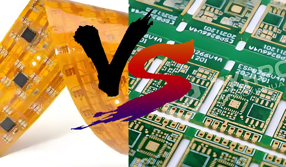
In today’s era of increasingly miniaturized and multi-functional electronic devices, circuit boards, as the “skeleton” and “nerve hub” of electronic components, their performance and form directly affect the overall performance of the device. Flexible Printed Circuits (FPC) and Rigid Printed Circuits (PCB) are two common types of circuit boards, with significant differences in materials, structure, performance, and applicable scenarios. This article will conduct a detailed comparison between the two from the dimensions of definition, materials, structure, design, performance, process, cost, application, advantages and disadvantages, to help you better understand the differences between FPC and PCB and provide reference for electronic device design and selection
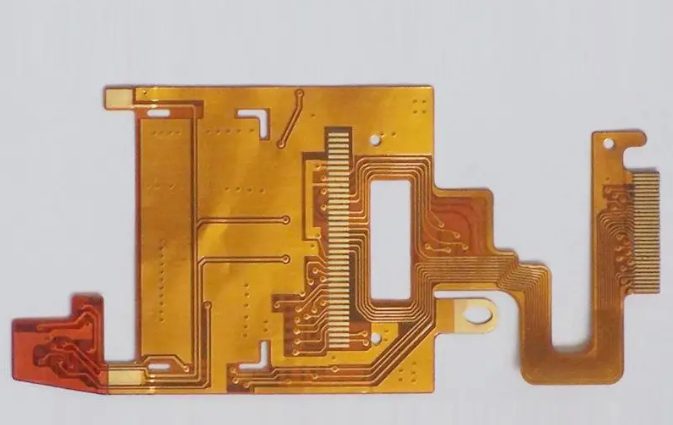
Flexible Printed Circuit (FPC)
FPC (Flexible Printed Circuit) is a type of circuit board with conductive circuits formed on a flexible insulating substrate through processes such as etching. Its most prominent feature is that it can be bent, folded, and curled, able to adapt to complex spatial layouts, and even maintain stable electrical connections in dynamic environments. For example, FPC is often used to achieve “small space, high flexibility” connections between the screen and the main board of smartphones, and in the internal circuits of smart watches. FPC circuit boards and flexible circuit boards are common names for it.
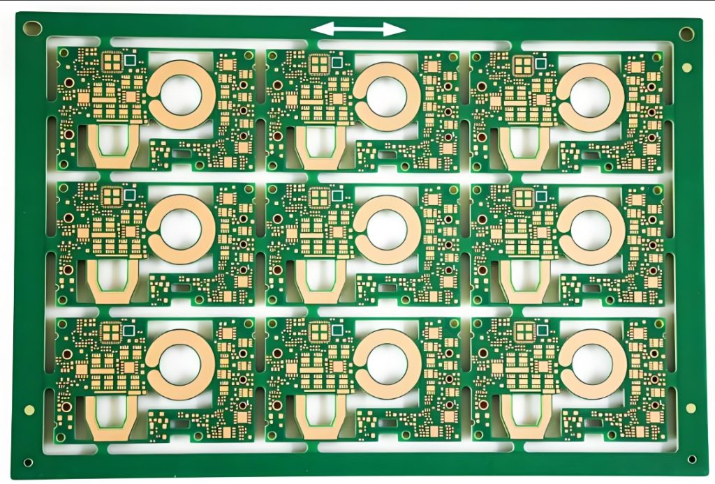
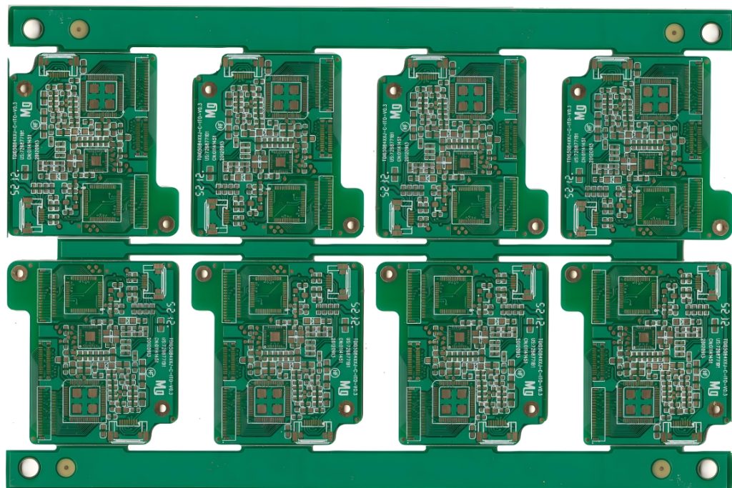
Printed Circuit Board (PCB)
PCB (Printed Circuit Board) usually refers to rigid printed circuit boards, with a hard insulating material as the substrate. The overall form of the board with attached circuits and components is fixed and cannot be bent or folded. It is the most traditional and commonly used form of circuit board in electronic devices, and can be seen from computer motherboards to home appliance control boards. PCB circuit boards and rigid circuit boards are also common names for it.
FPC vs PCB Core Difference Comparison
Materials
FPC
Substrate: Made from flexible materials like Polyimide (PI) and Polyester (PET).
Conductive Layer: Utilizes copper foil, mainly rolled copper or electrolytic copper.
Insulating Layer: Comprises polyimide film, adhesive, etc.
PCB
Substrate: Constructed with glass fiber cloth and epoxy resin, with FR-4 being the most prevalent type.
Conductive Layer: Features electrolytic copper foil, which is thicker compared to some alternatives.
Insulating Layer: Includes materials such as epoxy resin and phenolic resin.
The substrate of FPC needs to balance flexibility and high-temperature resistance. Polyimide (PI) is the mainstream choice, which can withstand temperatures above 200°C and has excellent insulation properties, giving FPC unique application advantages in many electronic devices.
The substrate of PCB is mainly FR-4, which has strong rigidity and high mechanical strength, and can support the welding and fixing of a large number of electronic components, being a widely used basic material in the electronics manufacturing industry.
FPC vs PCB Physical Structure
FPC: It has a thin and light structure, usually with a thickness between 0.1-0.3mm, composed of “flexible substrate + conductive circuit + cover film”. Some products will add a reinforcing plate (a local hard material for easy component welding). The overall bending radius is small (minimum up to 0.1mm), able to adapt to three-dimensional spatial layouts. This unique physical structure makes FPC shine in electronic devices with small spaces.
PCB: It has a relatively thick structure (conventional thickness 0.8-2.0mm), composed of multiple layers of hard substrates stacked and pressed together. Each layer is electrically connected through metallized holes (vias). The overall hardness is high, the form is fixed, cannot be bent, and needs to be fixed inside the device through brackets or shells. Its structural characteristics determine its important position in electronic devices that require stable support.
FPC vs PCB Design Features
FPC:
The core of the design is “spatial adaptation”, which needs to consider factors such as bending radius, number of folds, and dynamic stress to avoid circuit breakage. This design feature enables FPC to well meet the needs of device miniaturization and integration.
The circuit layout is more flexible, able to be “closely designed” along the contour of the device, saving space and improving the utilization rate of the internal space of electronic devices.
The number of layers is small (mostly 1-4 layers). Due to the limitation of flexible substrates, it is difficult to design with a high number of layers.
PCB:
The PCB design focuses on “high-density integration”, able to support multi-layer circuits (commonly 4-16 layers or even more), and achieve complex circuit connections through vias, able to meet the needs of large electronic devices for complex circuits.
It needs to consider the weight, heat dissipation, and mechanical fixing of components, and the layout must conform to the “rigid structure stability” principle to ensure the stable operation of electronic devices.
FPC vs PCB Performance
Electrical Performance:
FPC: The circuits are thin (minimum line width/line spacing up to 3/3μm), with high signal transmission efficiency, suitable for high-frequency signals (such as 5G devices); however, due to the thin substrate, its anti-interference ability is relatively weak, and an additional shielding layer needs to be designed, having certain advantages in the field of high-frequency signal transmission.
PCB: The circuits can carry large currents (thick copper foil), with strong anti-interference ability (can design ground layers and shielding layers), suitable for high-power and high-voltage scenarios (such as power boards), able to provide stable electrical support for high-power electronic devices.
Mechanical Performance:
FPC: It is resistant to bending (can withstand tens of thousands of folds) and vibration, suitable for dynamic environments (such as robot joints, automobile engine compartments); however, its mechanical strength is low, easy to be torn or stretched and damaged, performing excellently in electronic devices in dynamic working environments.
PCB: It has strong rigidity, impact resistance, and tensile resistance, able to support heavy components (such as capacitors, chips); however, it cannot be bent, and is prone to circuit breakage due to stress concentration when vibrated, playing a better role in electronic devices that need to withstand a certain external force.
Environmental Adaptability:
FPC: It is resistant to high and low temperatures (-55℃~125℃) and chemical corrosion, suitable for harsh environments (such as aerospace equipment), having strong environmental adaptability.
PCB: Its temperature resistance is slightly lower (the upper limit of conventional FR-4 is 130℃), but its moisture-proof and dust-proof performance is more stable, being widely used in electronic devices in daily environments.
FPC vs PCB Process
FPC Process:
Substrate pretreatment (cleaning the flexible film);
Laminating copper foil (bonding the copper foil to the substrate through adhesive);
Circuit etching (forming conductive patterns through photolithography + chemical etching);
Covering the insulating layer (attaching polyimide film to protect the circuit);
Reinforcement (locally pasting hard materials for easy welding).
Process difficulty: The flexible substrate is prone to deformation, requiring precise control of etching and lamination pressure. Exquisite craftsmanship ensures the excellent performance of FPC.
PCB Process:
Substrate cutting (cutting FR-4 sheets);
Drilling (drilling through holes or blind holes for interlayer connection);
Copper deposition/copper plating (plating copper in the holes to achieve conductivity);
Circuit etching (similar to FPC, but with thicker copper foil);
Lamination (multi-layer boards require high-temperature and high-pressure lamination);
Solder mask and silk screen printing (covering with green oil and marking component information).
Process difficulty: The alignment of layers in multi-layer boards and the quality control of vias. Mature technology enables large-scale production of PCB.
FPC vs PCB Cost
FPC: The cost is relatively high. The main reasons are that flexible substrates (such as PI) are expensive (about 5-10 times that of FR-4), the process is complex (such as precision etching, reinforcement lamination), and mass production is difficult. For small-batch production, the unit price may be 3-5 times that of PCB of the same specification. However, considering its irreplaceability in specific scenarios, there is still a stable market demand.
PCB: The cost is relatively low. FR-4 substrates are cheap, the process is mature, and mass production efficiency is high (a production line can have a daily output of thousands of pieces). The cost of multi-layer PCBs increases with the number of layers, but overall it is still lower than FPC of the same complexity, which makes PCB occupy a large share in the electronic market.
FPC vs PCB Application Fields
FPC Applications:
Consumer electronics: Smartphones (screen cables, camera connections), smart watches (internal circuits of the body), laptops (touchpad cables). FPC makes these consumer electronic devices more lightweight and portable.
Automotive electronics: Vehicle camera circuits, flexible connections for instrument panels, improving the reliability of automotive electronic systems.
Medical equipment: Wearable monitoring devices (such as heart rate bracelets), internal circuits of minimally invasive surgical robots, providing possibilities for the miniaturization and precision of medical equipment.
Aerospace: Lightweight circuits for satellites and drones, meeting the strict requirements of aerospace equipment for weight and performance.
PCB Applications:
Consumer electronics: Computer motherboards, TV driver boards, router circuit boards, which are core components for the normal operation of these devices.
Industrial control: Machine tool control panels, sensor circuit boards, ensuring the stable progress of industrial production.
Energy equipment: Charging pile control boards, inverter circuit boards, playing an important role in the energy field.
Communication equipment: Base station motherboards, switch backplanes, supporting the smooth operation of communication networks.

FPC vs PCB Advantages and Disadvantages
FPC vs PCB Advantages and Disadvantages
Advantages and Disadvantages of FPC
Advantages:
Good flexibility, able to adapt to complex spatial layouts, which is the most significant advantage of FPC.
Thin and light (weight is only 1/3-1/5 of that of PCB of the same area), conducive to device miniaturization, conforming to the development trend of electronic devices.
Resistant to vibration and fatigue, suitable for dynamic environments, improving the stability of the device in dynamic environments.
Fine circuits, high signal transmission efficiency, able to meet the needs of high-frequency signal transmission.
Disadvantages:
High cost and difficulty in mass production, which to a certain extent limits its application range.
Low mechanical strength, easy to be damaged, requiring proper protection.
Limited number of layers, not suitable for high-power and high-integration scenarios, with limited application in some large devices.
Difficult to repair (mostly need to be replaced as a whole when damaged), increasing maintenance costs.
Advantages and Disadvantages of PCB
Advantages:
Low cost, mature process, high mass production efficiency, suitable for large-scale production.
High mechanical strength and good support, able to stably support various electronic components.
Can be designed with multi-layer circuits, suitable for high-integration and high-power scenarios, meeting the needs of complex circuits.
Easy to repair (local replacement of components or circuits is possible), reducing maintenance difficulty and cost.
Disadvantages:
Rigid and fixed, unable to bend, with poor spatial adaptability, limited in application in devices with small spaces.
Heavy weight, not conducive to device lightweight, not meeting the lightweight needs of some devices.
Weak vibration resistance, prone to fracture due to stress concentration, requiring additional protective measures in vibrating environments.
FPC or PCB How to Choose?
FPC and PCB are not substitutes but complementary: when the device needs “flexible connection, lightweight, and small space”, FPC is preferred; when pursuing “low cost, high integration, and high stability”, PCB is a better choice. With the development of electronic devices towards “flexibility and wearability”, the application scenarios of FPC will continue to expand. However, as a traditional core component, PCB will still occupy a dominant position in most rigid devices. In actual design, the two can even be used in combination (such as “FPC + PCB” hybrid boards) to balance flexible connection and rigid support, providing more comprehensive solutions for the development of electronic devices.


0 Comments