




Conformal coating thickness is the thickness of the protective film left on an assembly, not the number of spray passes or how glossy the board looks. Specify the coating product, the dry-film range, the measurement locations and the acceptance method together. A thickness result without those details is difficult to use for releasing a production lot.
The practical goal is repeatable protection without missed areas, trapped solvent or coating on functional interfaces. This guide separates three questions: how much material remains, where it covers the assembly, and whether the specified cure is complete.
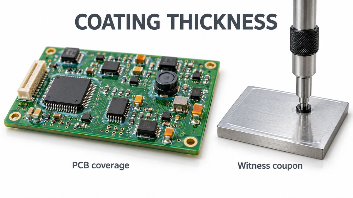
How thick should conformal coating be?
Use the approved product data sheet and your assembly drawing, not a universal number taken from another coating. Chemistry, application method, operating environment and qualification requirements affect the choice. If the drawing says only “apply conformal coating,” resolve the missing thickness and inspection requirements before ordering production.
Write the requirement as a controlled instruction: “Product and revision: ___; dry-film range: ___ micrometres; measurement method: ___; locations or coupon arrangement: ___; cure schedule: ___.” Ask the supplier to identify any conflict between the drawing and the coating manufacturer’s instructions. Do not silently choose the broader range.
Keep units explicit. One mil is 0.001 inch, or 25.4 micrometres; it is not one millimetre. A hypothetical 40-micrometre film is about 1.57 mils. This conversion changes the unit, not the acceptance tolerance or the measurement uncertainty.
Wet film vs dry film thickness: what is the difference?
Wet-film thickness describes the freshly applied material. Dry-film thickness describes what remains after the specified drying or curing process. Comparing a wet reading with a dry-film limit can make an otherwise controlled process appear incorrect.
| Check | Wet film | Dry film | Decision it supports |
|---|---|---|---|
| When measured | During application, before substantial evaporation | At the defined post-process condition | Adjustment during coating vs acceptance afterward |
| Suitable surface | Accessible representative test area or coupon | Area compatible with the selected gauge | Do not force a tool between populated components |
| Main limitation | Contact tools disturb the wet film | Substrate and geometry can bias a reading | Qualify the method before using its results |
| Relationship | Includes material that may evaporate | Cannot be inferred from pass count alone | Validate the application recipe against actual measurements |
Elcometer explains that an estimated dry thickness can be calculated from wet thickness and volume-solids fraction. For a hypothetical coating with 50% volume solids, an 80-micrometre wet film predicts approximately 40 micrometres dry. This is a process estimate, not a substitute for the required acceptance measurement. Do not insert a weight-solids percentage or an unspecified “solids” value into that calculation.
MG 422B aerosol: which parameters control the coating?
The MG Chemicals 422B Aerosol technical data sheet, version 5.0 dated 6 August 2025, provides a concrete example. These values apply to that acrylic-silicone aerosol, not every silicone coating or another supplier’s manufacturing capability.
| Parameter | Published value | Process implication |
|---|---|---|
| Recommended film thickness | 25–75 µm | Confirm the approved dry-film inspection requirement |
| Minimum recoat interval | 3 minutes | Allow the specified interval between coats |
| Dry to handle | 8 minutes, one coat; 15 minutes, two coats | Handling time is not full cure |
| Room-temperature cure | 48 hours | Record the actual cure conditions |
| Heat-cure alternative | 10-minute flash, then 20 minutes at 65°C | Check assembly compatibility before heating |
The sheet does not state a ± tolerance for these times. Do not treat them as guaranteed timing tolerances or substitute a hotter, shorter cycle. Confirm the current revision and safety data sheet before use; solvent-based aerosol application requires appropriate ventilation and ignition control.
How do you measure coating thickness on a PCB?
DeFelsko’s PCB measurement guidance distinguishes direct measurement over a copper plane from measurement on a companion metal coupon. It also warns that ultrasonic measurement has limited PCB applicability because layered boards can produce false readings.
- Define the measurement site. Select accessible locations and record their coordinates or photographs. For the described eddy-current method, an unpopulated area over a copper plane is required.
- Establish the baseline. Zero on the uncoated solder-mask surface for that method. A reading that includes an unaccounted underlying layer is not the coating-only result.
- Use a coupon when access is unsuitable. Coat it alongside the board. Match the gauge method to its metal substrate: non-ferrous and ferrous coupons require appropriate probes.
- Preserve individual readings. Record locations, cure state, instrument identity and results against the agreed sampling plan. Investigate an outlier before deleting it or averaging it away.
A coupon is process evidence, not proof that coating reached every lead or component shadow. Ask how its placement represents the production fixture. For a new geometry, agree how direct board inspection and coupon results will be correlated before releasing a large batch.
Can UV inspection prove coating thickness?
No: a fluorescent image by itself is not a calibrated thickness measurement. It can support coverage inspection when the coating has a suitable tracer, but brightness also depends on the viewing setup. Save the thickness results separately from the coverage photographs.
In a Reddit discussion about applying coating around connectors, users describe the value of seeing where material has been applied. That is a useful inspection question, but a community photograph is not a production acceptance standard. Specify the lighting, viewing conditions and areas to inspect in your own procedure.
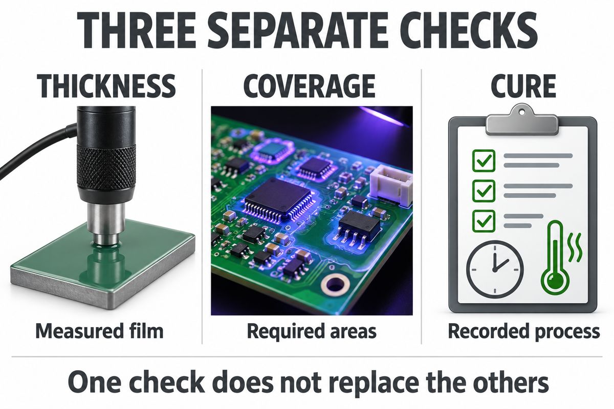
Review excluded interfaces as well as coated areas. A good thickness reading cannot compensate for material on a connector contact. Use the separate conformal coating masking checks when defining those boundaries.
What should you do about bubbles or uneven coating?
First identify the location, material and process condition. Do not diagnose a bubble as harmless, contamination or trapped solvent solely from a photograph. A discussion about needle-like dots on a coated board contains competing explanations, illustrating why an image needs supporting process evidence.
Place affected assemblies on hold under the applicable quality procedure. Compare the appearance with approved criteria, inspect whether a void exposes a critical area, and review the application and cure record. Then obtain an approved disposition: accept against documented criteria, rework using a compatible procedure, or reject. Avoid adding another coat simply to hide the symptom.
Use a first-article review for a new assembly or changed process. One LED-board discussion describes an entire batch coated before the requested sample approval. Set the approval hold point in the purchase order, including who may release production and which photographs and readings are required.
What should a coating acceptance report include?
Use this matrix as a supplier handoff checklist. It is a proposed record structure, not a universal sampling standard; fill in your product-specific limits and release authority before production.
| Record | Evidence to request | Question before release |
|---|---|---|
| Material identity | Exact product, lot and document revision | Does it match the approved specification? |
| Thickness | Locations, individual results, units, gauge and baseline | Are results within agreed limits using a valid method? |
| Coupon traceability | Coupon ID, board lot, fixture position and processing record | Was it processed with this lot, not separately? |
| Coverage and exclusions | Defined inspection views and defect locations | Are required areas covered and functional interfaces clear? |
| Cure | Actual schedule and relevant conditions | Was the approved process completed? |
| Disposition | Deviations, rework, reinspection and approval | Who accepted any exception, and on what basis? |
For an assembly review, send PCBtry your assembly files and coating requirements: board revision, BOM, coating product, two-sided coverage drawing, dry-film limits, cure restrictions and inspection plan. Ask which requirements can be supported and what evidence will accompany the lot before committing to production.
Conformal coating thickness FAQ
Is there one correct thickness for every conformal coating?
No. Start with the specific product and approved assembly requirements. A value suitable for one formulation is not automatically suitable for another chemistry or application method.
Does a thicker coating always provide better protection?
No. More material is not a replacement for qualified coverage and processing. Stay within the approved range and investigate defects rather than covering them with additional material.
Can I calculate dry thickness from wet thickness?
You can estimate it if the correct volume-solids fraction is available and the assumptions suit the process. Confirm the estimate against measurements; do not substitute weight solids.
Can UV brightness replace a thickness gauge?
Not without a separately validated measurement method. Treat ordinary UV viewing as a coverage check and keep numerical thickness evidence separate.
Does a passing coupon mean the whole PCB passes?
No. It supports the process record but does not prove coverage around all components, edges and exclusions. Board inspection remains a separate release requirement.
Is a dry-to-touch coating fully cured?
Not necessarily. Follow the specified cure schedule. Handling readiness and completion of the approved cure are different process states.
Are bubbles automatically acceptable if the thickness passes?
No. Evaluate their location and condition against the approved criteria. A thickness result cannot decide whether a local coverage defect is acceptable.
Can coating thickness alone prove electrical insulation safety?
No. A material’s dielectric-strength value is not an assembly safety approval. Do not use extra coating to bypass the product’s required insulation design, qualification or electrical tests.



0 Comments