




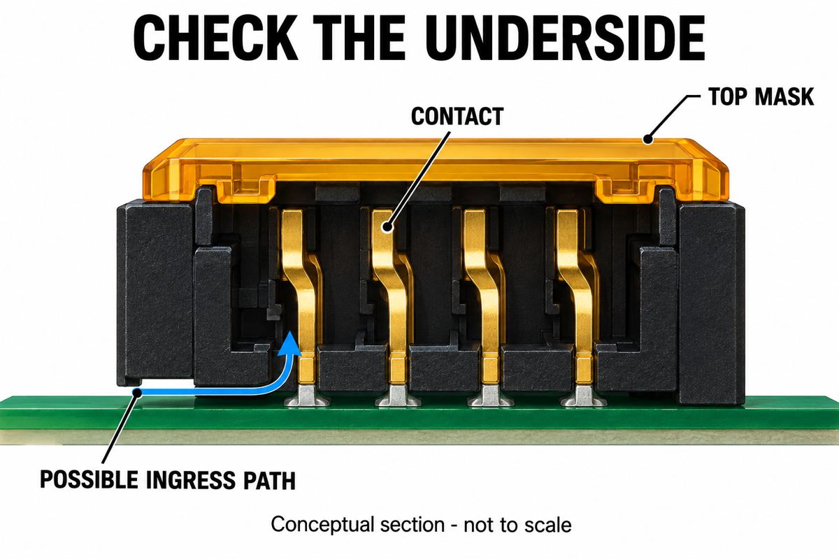
Conformal coating masking keeps insulating coating away from surfaces that must conduct, move, breathe or remain accessible. Start with a two-sided keep-out drawing, select a mask compatible with the actual coating and cure cycle, then verify that the mask can be removed without leaving residue or lifting the coating edge. Covering the visible connector opening alone does not prove that its contacts are protected.
The useful question is not simply “Which tape should I buy?” It is “Which surfaces must remain functional, and how will we prove they survived coating?” This guide turns that question into a masking plan and a release check.
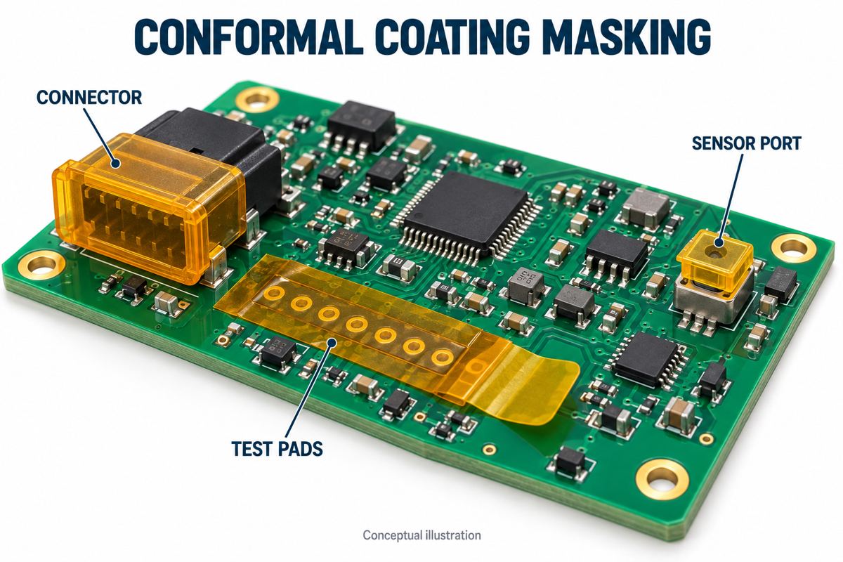
What should you mask before conformal coating?
Mask the interfaces that the product specification requires to remain uncoated. Typical candidates are mating contacts, edge fingers, programming pads, test points needed after coating, adjustable parts and openings used by sensors or acoustic devices. A sealed component and an apparently similar open component may need different treatment; use the exact part number and its manufacturer’s handling instructions.
Keep three functions separate. A connector housing supports the contacts; the mating surface carries the signal; its solder terminations attach it to the board. Permission to coat the solder joints does not automatically permit coating the contacts or filling the housing. Likewise, a pressure sensor needs access to the pressure being measured. Do not assume every metal-capped component is a sealed can.
A community discussion about coating a flight controller illustrates the confusion: advice to coat a plugged-in connector appears alongside warnings about wicking and excluded sensors. Those comments identify practical questions, not an approved manufacturing method. Resolve them using component documentation and a representative trial.
Also distinguish temporary masking from the board’s permanent solder mask. The green or other colored solder mask on a bare PCB is not a removable barrier for assembled connector openings. For the broader environmental decision, see PCB moisture-protection options.
How do you specify conformal coating keep-out areas?
Specify the protected surface, board side and acceptable coating boundary on an assembly drawing. “Do not coat J1” is incomplete if one person interprets it as the mating face and another excludes the entire body plus its solder joints.
Use a revision-controlled top and bottom view with reference designators. Add a side view when a gap underneath a housing creates a possible entry path. Do not adopt a universal keep-out distance: the needed boundary depends on geometry, coating flow, application accuracy and the product’s acceptance requirements.
- Identify: assembly revision, reference designator and exact component part number.
- Define: forbidden surfaces, permitted surfaces and any required bare access area.
- Locate: dimension the boundary from an unambiguous feature; state units and tolerances agreed with the coating provider.
- Plan removal: show an accessible tab or removal direction without pulling on a component.
- Verify: name the visual and functional check, acceptance limit and person authorized to release exceptions.
For example, a drawing note for a programming header can require clean mating contacts and unobstructed latch travel while separately identifying whether the solder side should be coated. This is more reproducible than a photograph with an unlabeled circle. If test pads will be contacted only before coating, engineering must explicitly decide whether they remain exposed afterward.
Masking tape vs boots vs peelable mask: which should you use?
Choose according to shape, entry paths and removal access, then qualify the complete material combination. The cheapest roll of tape is not necessarily the lowest-cost process if every board needs contact cleaning or edge repair.
| Method | Useful starting point | Check before approval |
|---|---|---|
| Tape or die-cut shapes | Flat pads, edge fingers and accessible boundaries | Adhesive compatibility, lifted corners, residue and coating-edge damage after removal |
| Reusable boot or cap | Repeated connector geometry across many boards | Actual fit, underside entry paths, wear and cleaning condition; a cap is not automatically a liquid-tight seal |
| Peelable temporary mask | Accessible irregular features that a flat shape cannot cover consistently | Mask cure, chemical compatibility and ability to recover every piece without trapping material |
Samtec’s connector-coating guidance explains why the underside matters: low-viscosity coating can enter housing openings around contacts. It also cautions about boot sealing during dipping and residue from peelable masks on fine-pitch features. Treat spray, dip and vapor deposition as different qualification cases, not interchangeable uses of the same mask.
A sensible trial compares two candidate masks on the same representative geometry using the intended cleaning, coating and cure sequence. Record application time, removal time, leakage and repair. Select based on the finished result, not just a material’s temperature rating.
Chemask HV CHV8: what do the published parameters mean?
Chemask HV is a named example of a temporary peelable masking material, not a universal recommendation. The following typical values come from the Chemtronics CHV8 technical data sheet, revision D dated December 2017. Confirm the current data sheet and lot requirements with the supplier before production.
| Parameter | Published value | Interpretation |
|---|---|---|
| Base and appearance | Natural latex rubber; pink | A temporary removable mask, not the final protective coating |
| Viscosity | Approximately 190,000 cP at 77 F (25 C) | Typical product data; qualify application on the actual feature |
| Tack-free time | 15 minutes at 10 mil thickness and 25 C | Tack-free does not mean fully cured |
| Cure time | 30 minutes at 10 mil thickness and 25 C | 10 mil is 0.254 mm; different deposits and conditions need validation |
| Solids content | Approximately 60% | Do not treat the wet deposit as an unchanged final geometry |
| Pack and shelf life | CHV8: 236 mL; stated shelf life 2 years | Check supplier storage instructions and lot expiry |
The manufacturer’s instructions require compatibility testing, including attention to bare copper, and removal after the mask has cured. These are mask properties, not a cure schedule for the conformal coating. The product’s wave-solder preheat claims must not be converted into a board-baking recipe. Read its SDS and use appropriate industrial ventilation, handling and ESD controls.
How do you mask, coat and remove the mask?
Use one controlled sequence from clean assembly to functional verification. Qualify the mask cure and coating removal window together; neither a generic waiting time nor a dry-looking surface proves that the combination is ready.
- Confirm the drawing and baseline function. Identify every exclusion on both sides. Check relevant connector, switch and sensor functions before coating so a pre-existing fault is not misdiagnosed as masking damage.
- Clean and dry using the approved process. Check compatibility with components and coating. Trapped contamination is not repaired by covering it. Use the PCB washing process checks when defining the upstream cleaning handoff.
- Apply and inspect the mask. Check continuous contact at the intended boundary, lifted edges and hidden openings. Leave a removal feature where practical. Do not push liquid mask into an inaccessible cavity to make it look sealed.
- Run a representative trial. Use the intended application direction, film build and cure conditions on an engineering sample. A flat coupon can screen compatibility, but it cannot prove a complex connector seal.
- Coat under the validated conditions. Record coating designation, batch, mask identity, application method and timing. A change of connector supplier, solvent or coating method can invalidate the earlier result.
- Demask within the approved window. Support the assembly and remove without levering against parts. Stop if the mask fragments, pulls the coating edge or remains trapped. Do not improvise with a knife near traces or flood the assembly with an unapproved solvent.
- Inspect, test and release. Reconcile removed pieces with the masking plan. Check coating edges and the functional interfaces before accepting the board.
The SCH masking methods guide similarly treats removal timing, adhesive behavior and repeatable application as process controls. For an engineering trial, write down the approved window rather than asking operators to judge “dry enough” differently on every shift.
How do you inspect a PCB after removing masking?
Inspect both the exposed interface and the adjacent coated area. A clean-looking top surface is not sufficient if coating or mask remains inside a connector. The table below is a proposed release-record template; replace its checks with the product’s approved criteria and test limits.
| Check | Record | Hold the board when |
|---|---|---|
| All exclusions demasked | Drawing revision, designators and removed-mask count where meaningful | A piece is missing or an inaccessible residue remains |
| Contacts and openings | Magnified inspection of accessible mating areas and vents | Film, adhesive or debris obstructs a specified functional surface |
| Coating boundary | Photos against the approved keep-out drawing | Edge lifting, tearing or an out-of-limit bare region requires disposition |
| Electrical interface | Specified continuity/contact-resistance or interface test results | Results miss product limits; do not invent one resistance limit for every connector |
| Mechanical and sensor function | Required latch, switch and sensor checks against baseline | Movement is restricted or output is outside the approved test limits |
| Repair and traceability | Authorized repair, retest, operator, date and material lots | Unapproved cleaning or repair has replaced a documented disposition |
If the coating contains a suitable fluorescent tracer, UV inspection can assist coverage checks under the supplier’s conditions. It does not prove electrical cleanliness, cure, adhesion or the absence of residue hidden inside a housing. A connector that passes one casual plug-in test is not automatically acceptable for its specified service life.
Conformal coating masking FAQ
Can you coat a connector while it is plugged in?
Do not assume mating creates a coating-tight seal. Examine the exact connector’s entry paths and manufacturer guidance. A production process needs a validated exclusion method and a post-coating interface check, not just a plugged-in sample.
Is polyimide tape always suitable for conformal coating?
No. The adhesive, coating chemistry, cure conditions and removal behavior matter as well as the backing. Approve the exact tape product after a representative compatibility and removal trial.
Do masking boots work for dip coating?
Only when the complete sealing arrangement has been qualified for dipping. A boot that shields spray from above may leave a liquid path underneath the connector.
Should barometers and microphones be covered?
Consult the component manufacturer. Openings needed for pressure or sound must remain functional. Identify the actual part first, define the exclusion and test it afterward; do not push masking compound into a port.
Is tack-free masking ready to remove?
Not necessarily. Tack-free and cured are separate states. Follow the mask’s requirements and the validated demasking window for the coating; the CHV8 example has different published tack-free and cure times under stated conditions.
Can peelable mask be placed underneath a BGA?
Do not put a temporary material where you cannot demonstrate complete removal. A Parylene masking discussion highlights exactly this concern. Resolve inaccessible regions with the coating provider and design authority rather than backfilling them experimentally.
Can the same masking plan be used for Parylene?
Not without separate qualification. Vapor deposition and liquid application expose different entry paths and process conditions. Agree the barrier, materials and removal method with the Parylene provider.
What should you do if tape lifts the coating edge?
Hold the assembly for inspection against its approved boundary requirements. Record the material combination and removal timing, obtain an authorized repair method and retest. Do not hide the tear under extra coating without resolving the cause.
What should you send for a coating review?
Send the assembly revision, BOM with exact connector and sensor part numbers, annotated top/bottom keep-out drawings, coating designation, proposed cure conditions, quantity and post-coating tests. Include photos of any previous leakage or residue and state which requirements are mandatory versus open for engineering review.
Contact PCBtry with your assembly files and masking requirements to discuss the project scope and confirm the available process before quotation. Ask for a first-article masking/removal record and agreed acceptance checks, not merely confirmation that the board will be coated.



0 Comments