




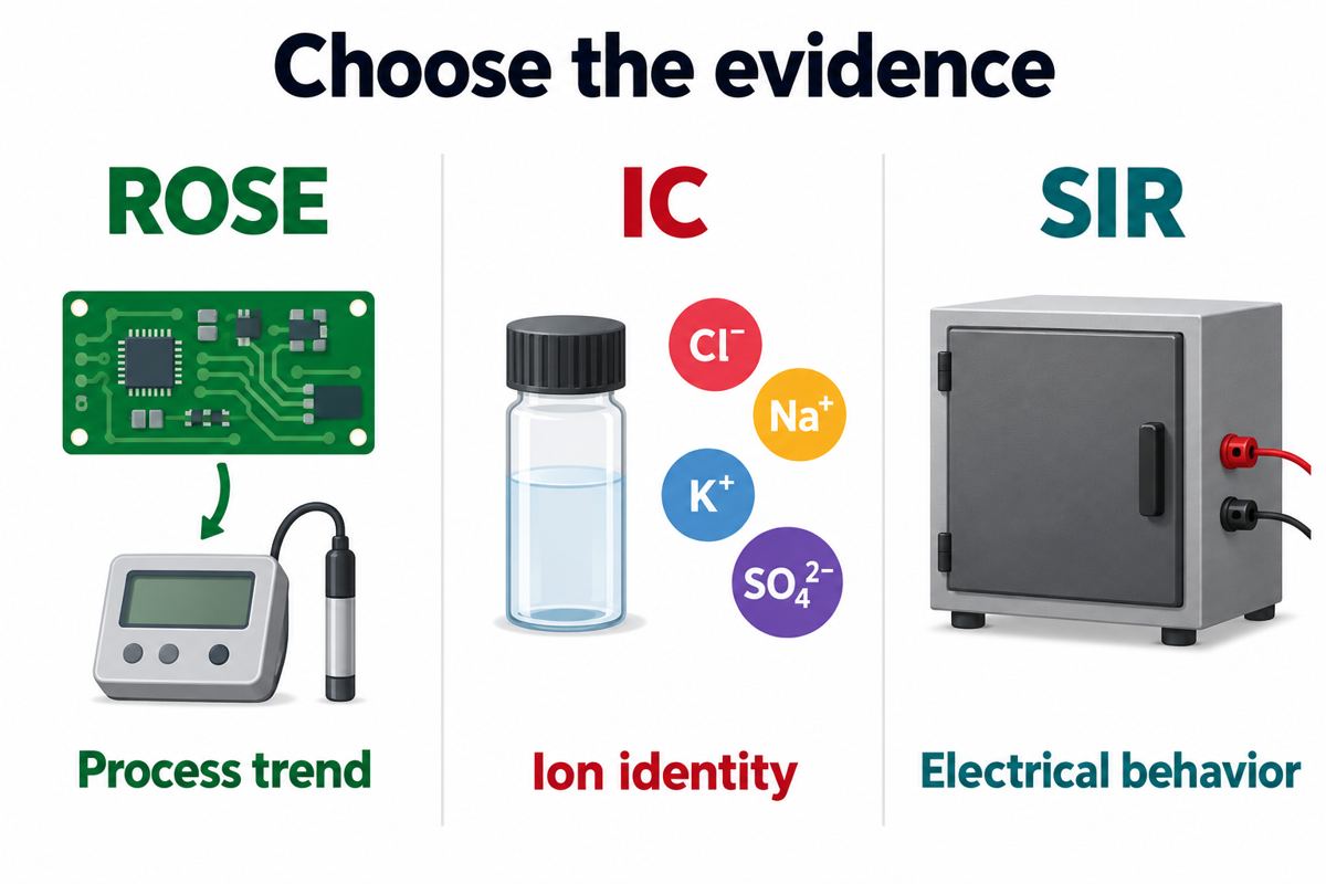
PCB ionic contamination testing checks residues that can become electrically active when moisture is present. Use ROSE for a repeatable bulk process-monitoring result, ion chromatography (IC) to investigate particular ions, and surface insulation resistance (SIR) testing to evaluate electrical behavior under defined environmental stress. These methods answer different questions; one passing number does not replace the others.

What does PCB ionic contamination testing measure?
It measures an aspect of contamination, not whether every part of an assembly is safe for its intended service. Begin by separating three questions: is residue visible, what can be extracted and measured, and how does the processed assembly behave electrically?
This distinction matters on a production line. In one Reddit production discussion, an operator described flux building up on fixture probes and causing repeated test problems. In another cleaning discussion, a user found that brushing with IPA left a dry but sticky board. These are useful symptoms, not chemical identifications: stickiness does not establish an ion concentration, and poor probe contact is not the same failure mechanism as leakage between conductors.
Record the observed symptom before choosing a test. A photograph, affected reference designators, process stage and failure conditions are more useful to a laboratory than the instruction “check if this board is clean.”
ROSE vs ion chromatography vs SIR: which test do you need?
Choose the method from the decision you need to make: monitor a stable process, identify contamination, or evaluate insulation behavior. Ask the laboratory to explain what its proposed result will not establish.
| Method | Useful question | Result to request | Important limit |
|---|---|---|---|
| ROSE | Has the monitored process changed? | NaCl-equivalent result with the same defined extraction setup and area basis | No identification of individual ions; not a reliability prediction |
| Ion chromatography | Which targeted ionic species are present? | Ion-by-ion results, extraction location and reporting limits | Only the sampled/extracted material and analytical scope are represented |
| SIR | Does the processed test vehicle retain insulation under the specified stress? | Resistance over time, test vehicle, bias, humidity and temperature | Not a chemical inventory or a guarantee of all field conditions |
IPC-TM-650 2.3.25D explicitly limits ROSE to process control. Its conductivity-based measurement does not identify individual species and misses material that is not extracted, as well as nonionic residue. Keep this boundary visible when reviewing a supplier’s certificate.
For IC, IPC-TM-650 2.3.28B addresses extractable ionic contamination. Specify the ions of interest rather than assuming every possible contaminant is included. ZESTRON describes both full-board and localized extraction; the latter can help investigate a particular trouble area instead of averaging it with the rest of the board.
A published Alpha/Bosch comparison of ROSE and SIR found that the methods could rank solder-paste residues differently. Treat that as a warning against substituting one measurement for another, not as a reason to discard process monitoring.
How do you read a PCB cleanliness test result?
Read the units, sample identity and method before reading “pass.” A result without its measurement context is not enough to compare two suppliers or release a lot.
NaCl equivalent is a calibration expression, not proof that sodium chloride is the contaminant. The reported conductivity is expressed relative to that reference. Also check the denominator: changing the stated surface area changes a result reported per square centimetre.
For example, imagine a laboratory reports a hypothetical total of 40 micrograms NaCl equivalent. Dividing by 100 cm2 gives 0.40 micrograms/cm2; dividing by 200 cm2 gives 0.20. Nothing became cleaner. This arithmetic example is not a measured PCB result or an acceptance recommendation. Agree how both board faces and component area are treated before comparing results.
Do not copy the familiar 1.56 micrograms/cm2 value from an old report and apply it universally. The cited Alpha/Bosch paper discusses it in a historical J-STD-001F context. Your purchase specification must identify the applicable document revision, approved process and acceptance criteria. If those are missing, ask the responsible quality engineer to resolve them before release.
GEN3 CM22 specifications: will your PCB assembly fit?
The CM22’s usable assembly envelope is smaller than its tank dimensions. Check the populated board, handling frame and minimum sample area together; a bare outline alone is insufficient.
| CM22 parameter | Published value | Practical check |
|---|---|---|
| Tank, width x height x depth | 250 x 370 x 60 mm | Do not treat this as the allowable populated-board envelope |
| Maximum PCB in handling frame | 215 x 330 x 33 mm | Include connectors, shields and components projecting from both faces |
| Minimum PCB area | 50 cm2 | Ask the laboratory how smaller samples are handled and reported |
Source: GEN3 CM brochure, 2024. Confirm the actual instrument configuration with the testing provider. This is a documented equipment example, not a statement that PCBtry owns a CM22.
For a hypothetical assembly measuring 200 x 300 x 40 mm, width and height fit the published frame envelope, but depth does not. Do not remove a connector merely to obtain a convenient result without an agreed sampling rationale: that would change the specimen being evaluated.
How should you plan PCB cleanliness verification?
Define the decision, preserve representative samples, and agree the test scope before anyone cleans or extracts the evidence. The following sequence is a practical handoff plan, not a replacement for a laboratory procedure.
Step 1: State the failure or release question. Separate a production trend, intermittent fixture contact, moisture-related leakage and coating preparation. Include when the symptom appears and what changed.
Step 2: Identify the process history. Provide solder paste and flux identifiers, reflow or hand-soldering stages, cleaning chemistry, rinse/dry records and rework history. The PCB washing process should be controlled independently of the measurement used to evaluate it.
Step 3: Agree the sample set. Identify lot, revision and process stage. Keep suspect samples separate from known-good references. Ask the lab about packaging and handling; do not preclean a failure sample unless that intervention is part of the plan.
Step 4: Select evidence and limits. Agree extraction scope, reporting units and required species for IC. For SIR, define the representative vehicle and stress profile. Indium’s SIR discussion explains why spacing, bias, environment and duration matter; a material’s published pass result does not automatically qualify your full assembly process.
Step 5: Review changes before release. If results depart from the approved baseline, investigate the change instead of repeatedly washing and retesting until a number passes. Preserve the first result, corrective action and justification for any retest.
What should a PCB contamination test report include?
A useful report connects each measurement to a specimen, a method and an authorized decision. Use this checklist during supplier review.
| Report item | What to verify | When to pause acceptance |
|---|---|---|
| Specimen traceability | Assembly revision, lot, quantity and process stage | The tested samples cannot be linked to your order |
| Method and extraction | Revision, instrument, whole-board or local scope, relevant conditions | Reports are compared despite different or undocumented methods |
| Units and area | Area convention, concentration or area-normalized result | Unit conversion or area basis is unclear |
| Analytical quality | Blank/control and calibration information; IC reporting limits where applicable | Background contamination or an out-of-range result is unresolved |
| Acceptance authority | Approved limit, specification revision and responsible reviewer | “Pass” has no identified criterion |
| Disposition | Original result, investigation, retest rationale and lot decision | Only the final passing retest is supplied |
Keep the completed checklist with the build records. For a new PCB assembly project, establish the required verification scope during quotation so that sample consumption, external laboratory work and reporting needs are agreed before production.
PCB ionic contamination testing FAQ
Does a sticky board mean it will fail an ionic test?
No. Stickiness is an observation, not an ion measurement. Document where the film appears and which flux or cleaner was used. The laboratory may need chemical or surface analysis in addition to an ionic test. Avoid calling the board safe or unsafe solely because the surface feels sticky.
Does no-clean flux remove the need for verification?
No. The material name does not answer whether your actual soldering, rework and service conditions are qualified. Ask for evidence covering the process being used. Probe contact and coating compatibility are also separate concerns; a residue may create a production problem without that problem being diagnosed by a bulk ionic result.
Can a multimeter replace a cleanliness test?
No. A resistance reading between accessible nodes does not identify extracted ions or reproduce a defined environmental qualification test. Use a multimeter for the electrical checks appropriate to the circuit, but do not convert that reading into a cleanliness certificate. Agree the required laboratory evidence with the quality owner.
Why can a board pass functional testing but still need contamination checks?
A functional test demonstrates specified operation under its test conditions. It may not expose the board to the humidity, bias duration or other stresses relevant to contamination. Conversely, residue on test pads can interfere with contact. Keep functional coverage, fixture maintenance and contamination verification as separate lines in the control plan.
Does a NaCl-equivalent result identify the source of contamination?
No. It expresses a conductivity response relative to a reference, not a chemical fingerprint. When the source matters, discuss targeted IC analysis and comparative samples with the lab. A measured species can narrow an investigation, but process history is still needed to determine where it entered the assembly.
Can several small PCBs be tested together?
Possibly, if the equipment and approved sampling plan allow it. GEN3’s CM guidance discusses combining small pieces to meet its minimum sample area. Record the number and identity of boards. A pooled result must not be presented as an individually measured result for every board in that group.
Will conformal coating fix an unresolved cleanliness issue?
Do not use coating as a substitute for resolving the issue. Establish whether the surface preparation and coating process are suitable together, and obtain the required verification before encapsulating evidence. A completed coating step does not explain an earlier unexplained ionic result or authorize shipment against a missing acceptance criterion.
What should I do after an unexpectedly high result?
Follow the agreed hold and investigation procedure. Check sample identity, area entry, blank/control information and method consistency, then review process changes with the responsible engineer. Do not discard the original record or authorize repeated retests without a rationale. The disposition should explain whether the issue was analytical, sampling-related or process-related.
Request a PCB assembly cleanliness review
Send PCBtry the Gerber files, BOM, assembly drawings, quantities and intended operating environment, together with any cleanliness specification or existing test report. Identify sensitive nodes, low-standoff components and coating requirements. Request an assembly and verification-scope review before ordering. Confirm the test method, acceptance limits, laboratory arrangements and report deliverables in the quotation; do not assume specialist testing is included by default.



0 Comments