




What are PCB tooling holes used for?
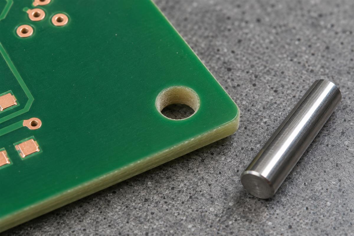
PCB tooling holes are mechanical reference holes that let pins locate a board or panel in a manufacturing, assembly or test fixture. Choose their finished size, position and clearance from the equipment that will use them. A familiar hole diameter is not enough: the board must fit the pins, sit on its supports and remain accessible at the correct production stage.
Think of a locating pin as a repeatable starting point. It tells the fixture where the board is. A clamp then holds the board against its supports; forcing a badly fitting board down with a clamp does not correct the underlying geometry.
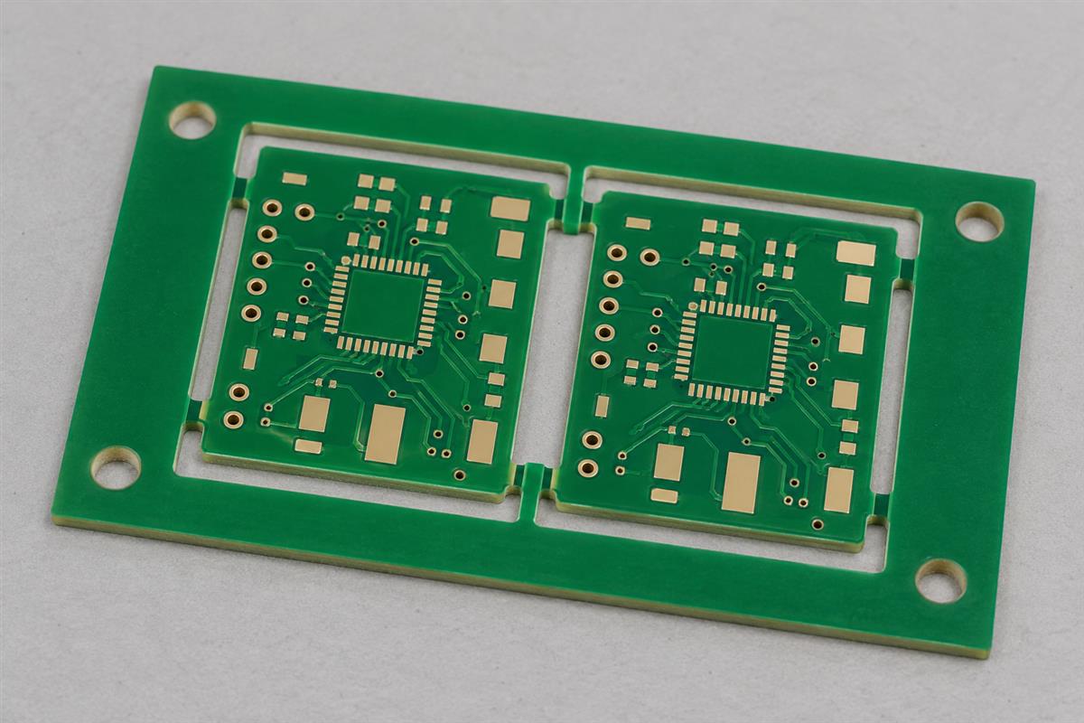
| Feature | Main job | What must be defined |
|---|---|---|
| Tooling hole | Engage a mechanical locator during a specified operation | Finished hole, pin fit, position and accessible area |
| Mounting hole | Attach the finished board to hardware or an enclosure | Fastener, loads, clearances and any electrical connection |
| Fiducial | Provide an optical reference for machine vision | Visible target and surrounding optical clearance |
A fiducial is not a small tooling hole. Eurocircuits describes fiducials as copper-layer targets used by placement and printing equipment. A camera reads the target; a physical pin engages a hole. Your assembly plan may need both.
Should tooling holes be on the panel or the finished board?
Put the reference where it still exists when the equipment needs it. Panel rails can carry production tooling holes, but a test performed after depaneling may need references on the individual board or another approved locating method.
Altium’s tooling-hole guide focuses on holes in panel rails and coordinating the panel with the manufacturer. That is useful for panel processing. It is not sufficient evidence that every finished PCB can dispense with fixture references.
For a different operation, Genesys Industries’ test-fixture guidelines discuss locating holes on individual boards as well as panels. The apparent disagreement disappears when you ask which object is being located and when it is tested.
For example, consider four boards joined in one assembly panel. Holes in the outer rails may serve a panel-level operation. If the rails are removed before final functional testing, those holes are gone. The test designer must either use approved board-level references or design another locating arrangement. Discovering this after the fixture is built can mean changing the fixture, board or test sequence.
Assign ownership before layout release: the fabricator owns its production panel, the assembler defines handling requirements, and the fixture designer defines test references. The customer-approved drawing must connect these decisions. Do not add factory-panel features to the product outline merely because a generic checklist mentions them.
How do you choose the hole diameter and tolerance?
Start with the mating pin and its permitted size range, then specify a compatible finished hole range. Also agree the hole locations: diameter controls local fit, while position controls whether several locators can engage together.
Different systems use different dimensions. The Eurocircuits eC-registration system specifies 3 mm finished location holes for its PCB and 5 mm holes for its stencil. Genesys’ cited fixture guidance prefers a 0.125-inch board hole. These are equipment-specific examples, not a universal PCB requirement.
Be careful with units: 0.125 inch equals 3.175 mm, not 3.00 mm. Rounding a familiar imperial dimension to a nearby metric size can make the wrong interface even before tolerance is considered.
For a simple round pin and round hole, calculate:
- Minimum diametral clearance = smallest permitted hole minus largest permitted pin.
- Maximum diametral clearance = largest permitted hole minus smallest permitted pin.
The following numbers are deliberately hypothetical teaching examples, not recommended tooling dimensions or PCBtry production tolerances.
| Assumed dimensions | Worst-case diameter difference | Meaning |
|---|---|---|
| Hole 3.00 +/- 0.05 mm; pin 2.98 to 3.00 mm | Minimum: 2.95 – 3.00 = -0.05 mm | An allowed hole can be smaller than an allowed pin |
| Same hole and pin ranges | Maximum: 3.05 – 2.98 = 0.07 mm | Other allowed parts can have clearance instead |
| Alternative hole 3.05 to 3.10 mm; same pin range | Minimum 0.05 mm; maximum 0.12 mm | Diameter clearance exists, but positional accuracy and restraint still need review |
A negative result identifies possible interference in this simple size check. A positive result does not prove the complete fixture will work. Hole position, pin spacing, angular misalignment, burrs and the permitted movement of the board remain outside this calculation. Diametral clearance is also not the same as radial movement; in an isolated concentric pair, the radial gap is half the diameter difference.
Specify whether the hole is non-plated or plated. Non-plated through-holes, or NPTHs, are commonly used for tooling, but the approved interface drawing is the authority. Eurocircuits’ drilling guidance distinguishes finished hole size from the production drill size and shows that default tolerances depend on the hole type. Do not assume an unspecified factory default satisfies a precision fixture.
Where should the holes go, and what can make the fixture bind?
Place holes so the fixture can locate and support the board without colliding with components, copper features, clamps or separation paths. Then check the relationship between the locators, not just each hole on its own.
Two individually acceptable holes can still fail to engage two pins if their centre spacing differs too much from the fixture. Making every hole a very tight fit can create redundant constraints. Carr Lane explains the round-pin and diamond-pin arrangement: one locator establishes two in-plane directions, while the relieved second locator controls the remaining rotation without duplicating both constraints. It is an option for the fixture designer, not a reason to alter an existing approved hole pattern on your own.
Use this placement review with the person responsible for the fixture:
- Choose the reference system. Identify the board surface and in-plane datums used by the fixture and inspection drawing.
- Check the actual loading orientation. Confirm the panel cannot be accepted in the wrong rotation or on the wrong side, or define a reliable detection method.
- Review the complete keep-out. Include the pin body, shoulder, clamp movement, underside components and support contacts, not only the drawn hole circle.
- Check rail and separation geometry. Ensure routing, tabs or V-scores do not remove or weaken a reference before its last use.
- Review support and restraint. Locating holes alone do not define where the board rests or how clamping and probe forces are carried.
There is no useful universal edge distance without knowing the rail, drilling process and fixture. State whether a quoted clearance is measured from the hole centre or its edge. For example, a 3 mm hole whose centre is 4 mm from a straight board edge leaves 2.5 mm between the nominal hole edge and board edge, before tolerances. That arithmetic explains the measurement; it does not establish an acceptable design margin.
What should the fabrication and fixture drawings specify?
Release one consistent package that connects the PCB geometry to the fixture interface. A CAD circle or drill entry with no purpose, tolerance or reference may be manufacturable yet unsuitable for the equipment.
| Drawing or file item | Required decision | Useful approval evidence |
|---|---|---|
| Board and panel revision | Which geometry is being built and at which stage it is located | Matching revision on PCB, panel and fixture drawings |
| Hole definition | Finished diameter range, plating status and quantity | Drill data and fabrication notes agree |
| Location requirements | Datums, coordinates and agreed positional controls | Fixture designer approves the mating pattern |
| Local environment | Copper/component keep-outs, access and rail/separation boundaries | Mechanical and assembly review of both board sides |
| Inspection and change control | How size, location and functional fit will be checked | Agreed first-article report and approval of later changes |
Before ordering, review the exported drill and outline files in a viewer. Confirm that NPTHs remain identified as non-plated, units are correct and the hole pattern is referenced to the intended outline. If the supplier proposes moving holes into a different rail or changing the panel arrangement, obtain fixture approval before accepting the revised files.
At first-article review, follow a short sequence: measure finished hole size with a suitable method, check locations against the agreed datums, then trial the board on the intended fixture. Record whether it seats without forcing and whether the assembly or test references remain aligned. A pin gauge checks a size condition; it does not, by itself, verify the whole pattern. Reject an unexplained forced fit instead of filing the holes until one sample works.
For the broader release boundary, see PCB DFM and DFA checks. When discussing a build with PCBtry’s manufacturing team, send the current fabrication files, panel drawing, finished-hole requirements and any existing fixture interface drawing through the contact page. Request confirmation of open dimensional questions before approving production; a quote alone is not approval of a mating fixture.
PCB tooling hole questions
Can an existing mounting hole also serve as a tooling hole?
Sometimes, if its finished size, position, access and condition suit both jobs. Check the actual fixture and mounting requirements together. A hole that clears a screw may allow too much movement for a locator, while plating or later-installed hardware can change the available interface.
Does every board need three tooling holes?
No universal count applies. Different tools use different locating and support arrangements. Define which features control position, rotation and support, then use the pattern approved for that process. Adding another tight locator without considering the existing constraints can make loading harder rather than more accurate.
Can I substitute a fiducial for a tooling hole?
Not when the equipment requires a pin to engage the board. A fiducial provides an optical reference, not mechanical restraint. A vision-based process may use a different fixture strategy, but that must be an agreed equipment decision rather than a layout substitution made from appearance alone.
Can the fabricator add tooling holes for me?
The fabricator may define features on its production panel. That does not automatically authorize changes to your finished board or satisfy a separate test fixture. State who owns the customer panel and which references must be preserved, especially when fabrication and assembly are handled by different suppliers.
Can I convert an imperial pin to the nearest metric hole?
Convert exactly first, then compare the full allowed ranges. A 0.125-inch nominal feature is 3.175 mm. A 3 mm nominal hole is a different size, not a harmless notation change. Match the approved pin and hole specifications rather than rounding to a convenient drill value.
Is passing a pin-gauge check enough?
No. It can verify a selected size limit but does not establish the relationship between several holes, the board outline and the fixture. Use dimensional inspection and a representative fixture trial as required by the acceptance plan. Preserve the measurement method and revision with the result.
What if assembly occurs before the panel rails are removed?
Rail holes may remain useful through that operation. Check what happens afterward: programming, functional testing or coating may occur on individual boards. The references needed by those later operations must survive depaneling or be replaced by a deliberately designed locating method.
Should I request the tightest tolerance available?
Request the tolerance the complete interface needs and can verify. A tighter hole diameter alone will not correct an incompatible pin pattern, poor support or an incorrect datum. Have the board supplier and fixture designer agree the size and location requirements together before committing to extra manufacturing cost.



0 Comments