
Let’s delve into two core concepts in PCB manufacturing: DFM (Design for Manufacturability) and DFA (Design for Assemblability).
They represent the most critical application of the “Concurrent Engineering” and “Design for X” philosophies within the electronics industry. Their goal is to prevent problems at the design source, thereby significantly reducing costs, shortening cycle times, and improving product quality.

DFM – Design for Manufacturability
1. Core Definition
DFM refers to the process of designing a Printed Circuit Board (PCB) while fully considering and optimizing the design to ensure it can be manufactured efficiently, cost-effectively, and defect-free through the entire production process at a PCB factory. It focuses on the production of the “bare board” itself.
In simple terms, it means making your design conform to the PCB manufacturer’s process capabilities and specifications, avoiding designs that are unproducible or have extremely low yield rates.
2. Why is DFM Critical?
- Cost Reduction: Problematic designs lead to lower yields, require special processes, and increase production time, all of which drive up costs.
- Improved Yield: Adhering to DFM rules avoids many common manufacturing defects, such as under-etching, shorts, opens, and lamination issues.
- Shorter Lead Times: Design files without DFM issues can quickly pass engineering review and enter production. Otherwise, repeated communication and design modifications cause significant project delays.
- Ensured Reliability: A design that conforms to manufacturing capabilities also possesses higher long-term reliability and stability.
3. Key DFM Considerations in PCB Manufacturing
DFM involves every step of PCB fabrication, primarily including:
- Trace Width/Spacing:
- Must conform to the factory’s processing capabilities. Traces that are too fine or too dense are prone to opens or shorts during etching.
- Current capacity determines the required trace width; DFM ensures the design meets both electrical performance and process requirements.
- Hole Sizes and Pads:
- Mechanical Drilling: Has minimum drill size limitations (typically 0.2mm or 0.15mm). The aspect ratio (board thickness/drill diameter) is also limited; if too high, it causes drilling difficulties and poor copper plating on the hole walls.
- Pad Size: Through-hole pads must have sufficient annular ring width to prevent break-out due to drill misalignment, which can lead to open circuits.
- Blind/Buried Vias: Have stricter DFM requirements for their structure and dimensions.
- Solder Mask and Silkscreen:
- Solder Mask Dams: A solder mask bridge must be maintained between adjacent pads (especially IC pins) to prevent shorts during soldering. DFM rules specify the minimum width for these dams.
- Silkscreen Clarity: Text line width cannot be too fine and must not be placed on pads, otherwise it will affect solderability.
- Lamination and Materials:
- Select appropriate substrate materials (e.g., FR-4, high-frequency materials, high-Tg materials) to meet the product’s electrical and thermal performance requirements.
- Consider copper foil thickness, as it affects current-carrying capacity and impedance control.
- Impedance Control:
- For high-speed circuits, impedance matching is crucial. DFM requires adjusting trace width, dielectric thickness, and dielectric constant to achieve target impedance values, aligning with the factory’s stack-up structure.
- Minimum Electrical Clearance:
- Based on the product’s voltage rating, the design must maintain sufficient clearance between different nets (e.g., between high and low voltage) to meet safety standards (e.g., UL, CE).
- Panelization Design:
- For small PCBs, panelization is often necessary to improve production efficiency. DFM governs the use of V-scoring or break-away tabs (mouse bites), and the addition of fiducial markers.
DFA – Design for Assemblability
1. Core Definition
DFA is the process of designing a PCB while fully considering and optimizing the placement, orientation, and package types of components on the board, enabling them to be assembled efficiently, accurately, and reliably by automated assembly equipment (e.g., pick-and-place machines, insertion machines, soldering equipment). It focuses on the process of “mounting components onto the board.”
In simple terms, it means making your design easy for both machines and operators to assemble and solder.
2. Why is DFA Critical?
- Improves Assembly Efficiency: Rational layout and orientation can reduce the pick-and-place path of SMT machines, shortening assembly time.
- *Example: Placing all identical 0805 resistors in the same orientation (0°) allows the pick-and-place machine to populate them sequentially without rotating the head or changing nozzles, saving valuable time per placement.*
- Reduces Assembly Defects: Avoiding placements that are difficult to inspect, rework, and solder significantly lowers the risk of cold joints, shorts, wrong parts, etc.
- Example: In wave soldering, placing a small capacitor immediately downstream of a large QFP creates a “shadow effect,” leading to insufficient solder on the capacitor pads.
- Lowers Assembly Costs: Higher automation and less manual intervention reduce costs. DFA design maximizes these efficiencies.
Comparison of DFM and DFA
| Aspect | 🔧 DFM | 🧩 DFA |
|---|---|---|
| Focus | Manufacture of the bare PCB itself | Assembly of components onto the board |
| Core Objective | Ensure the PCB is producible, high-yield, low-cost | Ensure the assembly process is efficient, reliable, and highly automatable |
| Involved Processes | Imaging, Drilling, Plating, Etching, Lamination, Solder Mask, Silkscreen, etc. | Solder Paste Printing, Component Placement, Reflow Soldering, Insertion, Wave Soldering, Testing, Rework, etc. |
Synergy
In practice, DFM and DFA are inseparable and must be considered simultaneously. Together, they form a broader concept known as DFX (Design for Excellence). Excellent design engineers must continuously balance and optimize manufacturing and assembly requirements during the design process.
Examples:
- To meet DFM impedance control requirements, trace width and stack-up may need adjustment.
- To meet DFA requirements, the placement of an IC might restrict routing space beneath it, affecting DFM routing difficulty.
- The panelization method considered in DFM must accommodate DFA soldering processes (e.g., component orientation requirements for wave soldering).
How DFM and DFA Work in PCB Manufacturing
When you submit PCB files, the manufacturer performs DFM/A checks using proprietary computer programs. This software identifies manufacturability and assemblability issues that need resolution before production.
Potential issues identified include improper component spacing or orientation. Designs must also comply with industry standards, which vary. The PCB manufacturer communicates these issues and discusses solutions.
PCB manufacturers also have internal design rules based on their technology and standards. They use these rules to define which designs will run smoothly.
💡 Core Understanding of DFM vs. DFA
To master DFM and DFA, first understand their respective focuses and how they work together.
- DFM (Design for Manufacturability): Focuses on the design of the individual part itself, ensuring it can be manufactured efficiently, economically, and with high quality. In the PCB field, this refers to the manufacturing process of the bare board. Its core is aligning the design with the PCB factory’s process capabilities, avoiding boards that are unproducible or have very low yield.
- DFA (Design for Assemblability): Focuses on how to efficiently and reliably assemble multiple parts into a complete product. In the PCB field, this refers to the process of installing various electronic components (like chips, resistors, capacitors) onto the bare board to form a PCBA (Printed Circuit Board Assembly). Its core is optimizing the layout to facilitate assembly by automated equipment (e.g., pick-and-place machines) and operators.
Despite their different focuses, DFM and DFA are closely linked in practice and are often collectively referred to as DFMA. DFM is the foundation for DFA—a poorly manufactured PCB cannot be assembled smoothly. DFA is the extension of DFM—an excellent, manufacturable design must also be easy to assemble subsequently.
The table below clearly compares the core considerations of DFM and DFA in PCB design:
| Dimension | 🔧 DFM – Design for Manufacturability (Focus on Bare Board) | 🧩 DFA – Design for Assemblability (Focus on Component Placement) |
|---|---|---|
| Focus Goal | Ensure the PCB is producible, high-yield, low-cost | Ensure the assembly process is efficient, reliable, and highly automatable |
| Key Parameters | Trace Width/Spacing: Conform to factory capabilities, avoid shorts/opens. Hole Size & Pads: Ensure min. hole size, aspect ratio, annular ring. Impedance Control: Adjust trace/stack-up for high-speed circuits. Solder Mask & Silkscreen: Maintain solder dams; clear silkscreen. | Component Layout: Sufficient spacing between components and from board edge. Component Orientation: Uniform orientation for similar parts. Land Pattern Design: Precisely match component package. |
| Process & Materials | Select substrate materials (FR-4, High-Tg) based on electrical/thermal needs. | Optimize layout based on process (Reflow/Wave Soldering) to avoid defects. |
| Auxiliary Design | Panelization: V-CUT/break-away tabs; tooling rails. Test Points: For ICT. | Fiducial Marks: For pick-and-place accuracy. Thermal Design: Manage heat dissipation. |
The Value and Process of Implementing DFM and DFA
Systematically applying DFM and DFA during the product design phase offers significant benefits.
Key Value of Implementing DFMA
- Significantly Reduces Costs: 75%-90% of a product’s cost is determined during the design stage. DFMA effectively controls costs by simplifying designs, reducing part counts, and avoiding late-stage modifications.
- Shortens Development Cycles: By “getting it right the first time,” DFMA can save an average of 39% in product development time, avoiding late-stage revisions and trial production loops.
- Improves Product Quality & Reliability: Mitigates manufacturing and assembly risks at the source, reducing defect rates and enhancing long-term stability.
General DFMA Implementation Process
- Early Planning & Team Collaboration: Involve manufacturing and assembly engineers from the very beginning of the product design phase for joint planning.
- Design Simplification & Part Standardization: This is the core of DFA. Minimize the number of parts and use standard components and modular designs to simplify assembly, reduce costs, and minimize inventory.
- Detailed Design Following Guidelines: During part design and layout, strictly follow various DFM and DFA design guidelines (e.g., ensuring uniform wall thickness, providing draft angles, designing stable bases and guiding features).
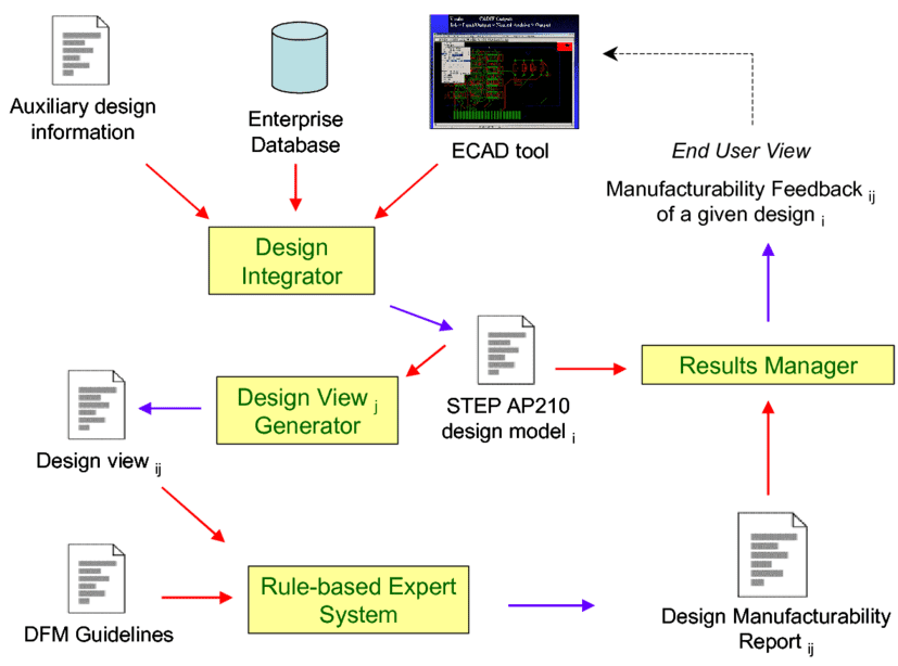
- Analysis Using Software: Utilize specialized DFM/DFA analysis software to virtually simulate and run rule checks on design data, identifying potential issues early.
- Iterative Optimization: Feed the analysis results back into the design for iterative optimization until all manufacturability and assemblability requirements are met.
Summary
In modern electronics development, neglecting DFM/DFA is like planting a time bomb in your project. It may detonate only after production has started, causing significant financial loss and project delays.
Best practices are:
- Communicate with your PCB manufacturer and PCBA assembly house early in the design phase to obtain their latest process capability manuals.
- Use DFM/DFA check tools within your EDA software to run rule checks before releasing drawings.
- Before sending out the design, commission a professional service or the factory itself to perform a DFM/DFA analysis—it is a highly cost-effective investment.
Integrating the principles of DFM and DFA into the design and development process is the key leap from achieving a “design that works” to a “design that can be made correctly.”


0 Comments