




Press-fit PCB holes must be specified from the exact contact or connector drawing, including finished plated-hole diameter and tolerance. Do not choose the hole simply by measuring a pin and subtracting a small amount. A connection that feels tight can still be the wrong termination, damage the hole, or vary across a production lot.
Start by identifying the pin technology, then compare the required hole window with what the fabricator will supply. The worksheet and release checklist below help a designer, buyer and assembler agree on the same requirements before boards are ordered.
Is a Tight Header the Same as a Press-Fit Connection?
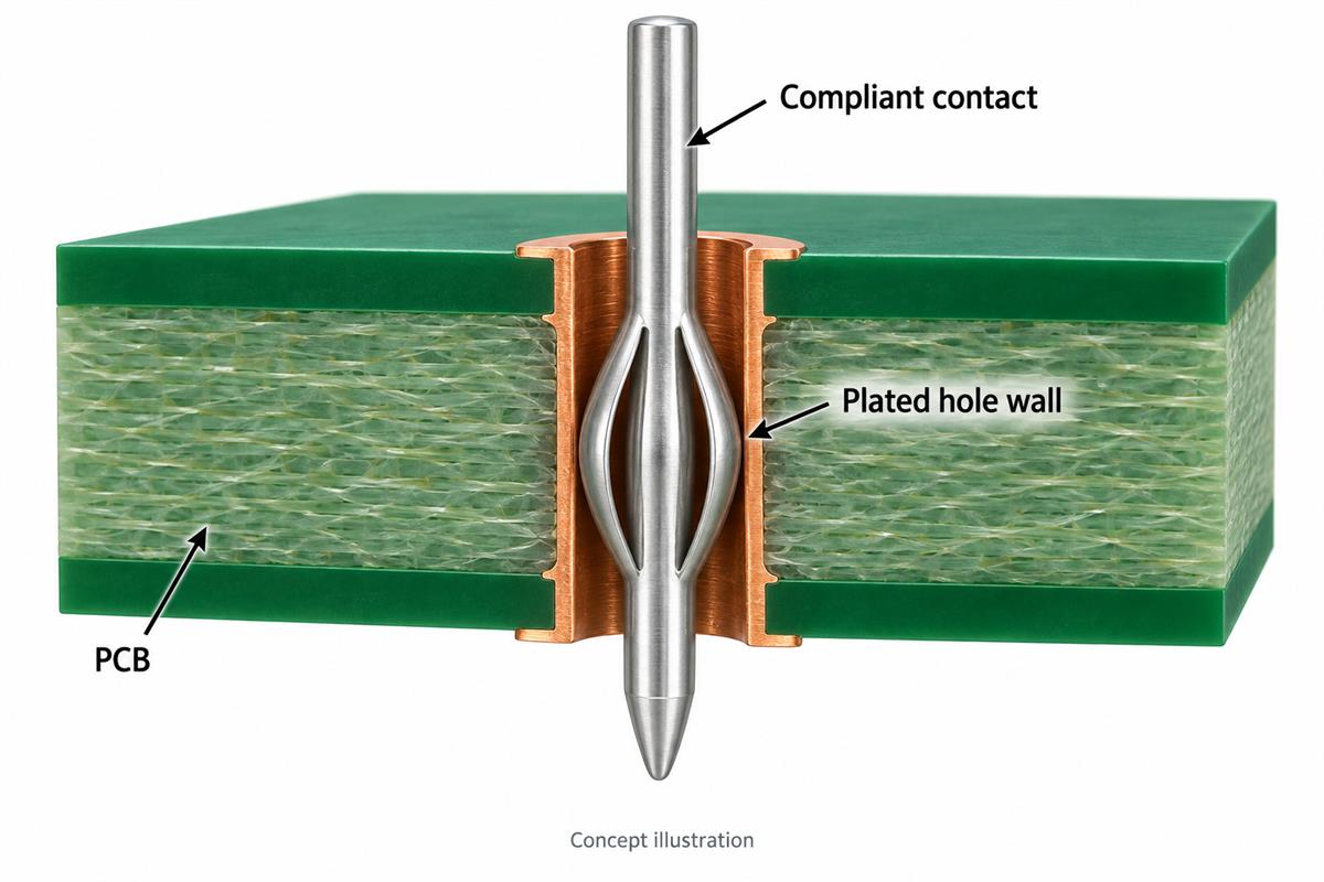
No. An ordinary header held by friction is not automatically a qualified solderless press-fit connection. In a compliant contact, a deliberately shaped flexible region compresses inside the plated through-hole. The pin and hole are designed to work together. Solid press-fit terminals also exist, but their construction and application instructions are different.
A Reddit programming-header discussion illustrates the confusion: a developer wanted a removable header to grip without solder, while replies described difficulties with repeated use and automated testing. That is evidence of a practical problem, not a qualification report for any connector.
Write the intended use at the top of your review: permanent electrical termination, temporary programming contact, or mechanical retention before soldering. These are different jobs. For temporary access, compare a connector or test fixture designed for repeated contact instead of assuming the PCB barrel is a reusable socket. For permanent assembly, obtain the manufacturer’s termination instructions and tooling requirements.
Samtec’s compliant-pin guidance describes a purpose-designed interference fit and product-specific processing. A library footprint or 3D model alone does not establish that your chosen header supports that process.
How Do You Specify the Finished Hole and Its Tolerance?
Specify the diameter after the required hole plating and finish, then have the fabricator confirm that its delivered interval fits entirely inside the connector’s allowed interval. Separately identify any drill-before-plating dimension required by the component manufacturer. Do not leave the two dimensions under the same ambiguous label.
In a PTH tolerance discussion, a designer tried to select one nominal diameter for a snug pin fit despite a broad fabrication tolerance. The useful lesson is to review the allowed extremes, not just the number at the center. Comments about enlarging holes or forcing pins are not substitutes for the part drawing.
| Record | Where to obtain it | Release question |
|---|---|---|
| Exact part number and drawing revision | Connector manufacturer | Does this drawing describe the purchased termination option? |
| Required finished-hole minimum and maximum | Application specification | Are both limits explicitly transferred to the fabrication drawing? |
| Offered finished-hole minimum and maximum | Fabricator’s written review | Is the whole offered interval inside the required interval? |
| Hole location, pattern and board thickness | Footprint and mechanical drawing | Will the complete connector align and seat, not just one pin? |
| Inspection method and acceptance record | Agreed quality plan | How will this feature be verified and linked to the board lot? |
Illustrative arithmetic, not a connector specification: suppose an application drawing permits 0.95-1.05 mm finished holes. An offer of 1.00 mm +/-0.08 mm permits 0.92-1.08 mm. Its nominal value looks correct, but both ends exceed the required window. An offer of 1.00 mm +/-0.04 mm fits that diameter window; it does not by itself approve plating, location, seating or electrical performance.
Ask for a specific capability review of the identified holes. Do not tighten every hole on the board unnecessarily, and do not silently edit the drill file to compensate for plating. Agree how the fabrication data expresses finished size; the PCB drilling guide provides the broader hole-production context.
Which Plating and Board Details Must Match the Connector?
The hole wall construction, surface finish and board thickness must match the requirements for the selected part. A compliant diameter is only one item in that specification. TE’s press-fit technology whitepaper treats the contact and plated hole as a system whose materials and processing interact.
As a concrete documentation example, the Wurth Elektronik 74622108 datasheet has separate hole callouts for chemical surfaces and HAL. Those are requirements for that terminal, not dimensions to copy into a different connector footprint. They show why a finish substitution deserves another review rather than a purchasing-only change.
For compliant contacts, check where the active region sits within the board. Samtec’s guidance warns that board thickness and hole construction in that region matter; a pin tip visible underneath is not the sole acceptance criterion. Ask the supplier to resolve any conflict between a generic footprint, an application note and the current part drawing before release.
Keep the fabrication review focused: identify copper-wall requirements, permitted finish, board thickness range and any hole-region restrictions from the actual specification. Use the plated through-hole process explanation for background, not as a source of connector-specific acceptance limits.
How Should Press-In Assembly Be Checked?
Use the component manufacturer’s approved insertion method and acceptance criteria, then record the result on representative production-intent assemblies. Hand pressure and a continuity beep are not a complete process qualification.
- Match the inputs. Confirm connector part/revision, PCB lot and the approved hole drawing before loading the job. Stop if a substituted part has a different termination.
- Review the support and press tool. Confirm the intended force path, board support and clearance for nearby components with the assembler. Wurth’s REDCUBE support note emphasizes supported, perpendicular insertion; its family-specific values must not be applied to unrelated pins.
- Run the approved stroke. Use the specified seating condition and process settings. Do not respond to unexpected resistance by improvising extra force.
- Inspect seating and pin condition. Check against the exact drawing, including accessible opposite-side features. Samtec specifically calls for checking that pins entered the board rather than buckling.
- Review process evidence. Where required, compare insertion force or force-distance data with approved limits. TE describes monitoring as a process-control tool; a normal-looking curve does not replace the rest of the acceptance plan.
- Release or contain. Link the inspection and test results to the PCB and connector lots. Hold questionable assemblies for engineering disposition instead of treating successful power-up as proof of long-term reliability.
What Goes in the Fabrication and Assembly Release Packet?
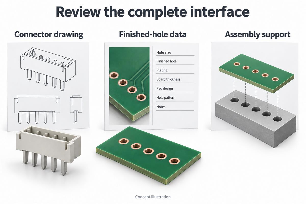
Send one consistent packet that identifies the critical holes, their governing specification and the evidence required before shipment. The following checklist is a review aid, not a replacement for your approved drawing or quality agreement.
- Exact connector part number, termination option and current application drawing.
- Gerber or agreed fabrication data, drill data and a marked critical-hole map.
- Finished-hole limits, location requirements and explicitly identified pre-plating dimensions where applicable.
- Stackup, finished board thickness, hole-wall requirements and permitted finish.
- Assembly drawing with orientation, seating requirements and nearby keepouts.
- Proposed tooling and support arrangement, with unresolved questions highlighted.
- First-article inspection, process-monitoring and electrical test requirements.
- Lot traceability, substitution approval and nonconformance disposition responsibilities.
| Observation | What it does not prove | Next action |
|---|---|---|
| One sample fits comfortably | All allowed pin and hole combinations will fit | Review tolerance extremes and the agreed sampling plan |
| A pin needs unexpected force | The connection is better because it is tighter | Stop; check identity, alignment, holes and tooling |
| Electrical continuity passes | Mechanical integrity and lifetime performance are qualified | Complete the agreed mechanical and process checks |
| The quoted finish changes | The original hole specification still applies unchanged | Obtain component and fabricator review before approval |
| A connector has been removed | The same holes and pins can be reused | Follow the exact manufacturer’s rework disposition |
Press-Fit PCB Hole FAQ
Can I use a caliper measurement of the pin to design the hole?
Use it to identify a discrepancy, not to replace the application drawing. The dimension you measure may not be the functional press-fit region. Obtain the part number and termination specification before selecting the hole.
Should the press-fit hole be listed as plated or non-plated?
For an electrical press-fit contact designed for a plated through-hole, identify it as plated. Mechanical pegs may have different requirements. Keep those features separately identified instead of applying one hole rule to the entire connector.
Can I use the same hole for two substitute connector brands?
Only after comparing their actual requirements and obtaining approval for both. Matching pitch and external shape do not establish an interchangeable press-fit interface. Record which part numbers the released footprint supports.
Does a CAD design-rule check approve the press-fit interface?
No. It checks the rules configured in the design, not an unstated supplier requirement. Verify that the fabrication drawing, footprint, BOM and assembly instructions all refer to the same approved interface.
Is a test-fit coupon useful?
It can help investigate assembly behavior if it represents the intended materials and process. It does not override the specified tolerance range or qualify every future lot. Agree in advance what measurements and decisions the trial will support.
Can I remove and insert the connector repeatedly?
Do not assume so. Permanent press-fit termination and a reusable mating interface are different functions. Get the manufacturer’s rework limits; use a suitably rated socket or test connection when repeated access is the requirement.
Can solder rescue a loose press-fit contact?
Do not add solder as an undocumented repair. Investigate the wrong part, hole or process first, then obtain a disposition for the exact assembly. A repair can change both the interface and the accepted manufacturing process.
What should purchasing ask when comparing quotations?
Ask whether each quote includes the marked critical-hole tolerances, specified finish, inspection evidence and assembly scope. A lower price with an unreviewed standard tolerance is not an equivalent offer.
Request a Hole-Specification Review Before Ordering
Send PCBtry your fabrication files, marked hole drawing, stackup, connector part number and application specification through the contact page. Include quantity and whether you need bare boards or assembly. Ask for written confirmation of the critical-hole requirements and any tooling or inspection limitations before placing the order.



0 Comments