
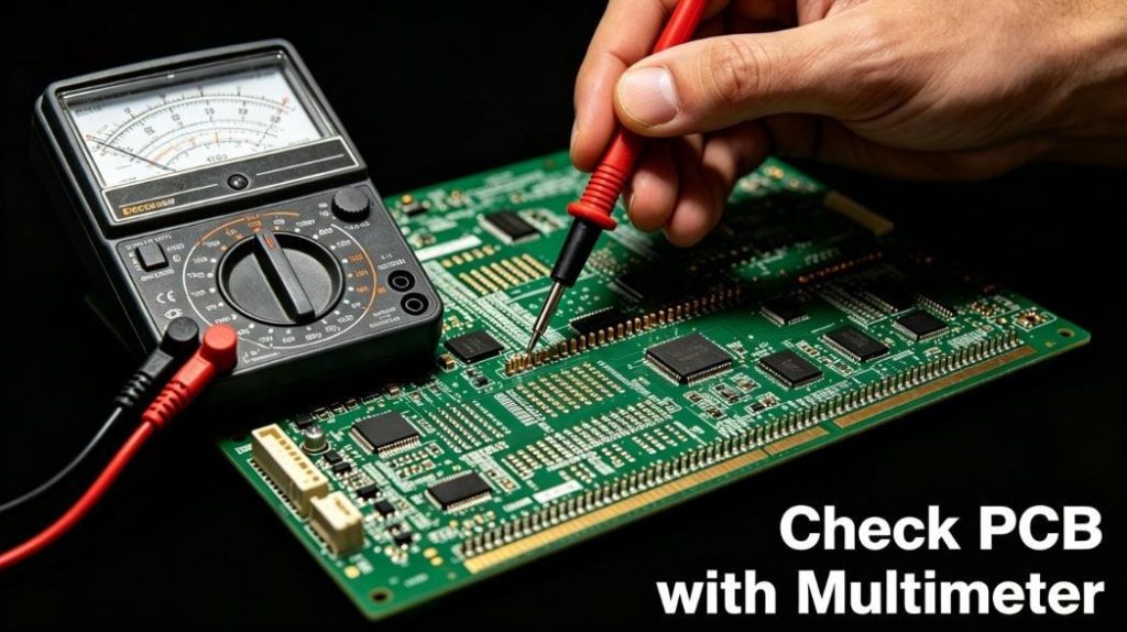
What Is the Best Way to Check PCB with Multimeter for Beginners?
Learning how to check PCB with multimeter is an indispensable skill for electronics practitioners. This standardized tutorial explains how to check PCB with multimeter using four mainstream testing modes to resolve common circuit failures. A digital multimeter remains the most user-friendly testing instrument for entry-level technicians.
It covers continuity, voltage, resistance, and component testing without complicated auxiliary equipment. Even users with zero PCB maintenance experience can complete basic troubleshooting following this guide.
Why Use a Multimeter for PCB Testing Instead of Other Tools?
Multimeters stand out for PCB inspection due to their cost-effectiveness, portability, and multi-functional integration. This tool covers over 80% of conventional PCB fault detection scenarios with a simple operating logic.
Unlike high-precision devices such as oscilloscopes, multimeters require no professional training. They adapt to both bare copper boards and fully assembled PCBs for daily engineering inspection.
Audible continuity alerts and intuitive digital readings also lower the judgment threshold for electronic circuit detection.
How to Perform Continuity Test on PCB Using Multimeter?
Continuity testing judges the electrical connectivity of PCB traces, vias, and soldering joints to identify open circuits rapidly. This is the most frequent test in daily PCB maintenance.
- Step 1: Switch the multimeter to dedicated continuity mode, marked with a buzzer symbol on the gear dial.
- Step 2: Place two probes separately on the start and end test points of the target trace.
- Step 3: A continuous beep indicates intact connectivity; no sound confirms an open circuit on the trace.
Gently move the probes along the trace to pinpoint tiny cracks or hidden breaking points for precise maintenance.
How to Measure Voltage on PCB with Multimeter (Step-by-Step)?
Voltage measurement applies to energized PCBs to verify whether power rails and chip pins receive rated voltage. It is the core method to diagnose power supply anomalies.
- Step 1: Turn the multimeter to DC voltage mode and select a reasonable range matching the circuit design.
- Step 2: Connect the black probe to the fixed GND point and the red probe to the detection pad.
- Step 3: Compare the stable reading with the standard circuit parameters such as 3.3V and 5V.
Abnormal voltage values directly reflect power line drops, short circuits, or abnormal IC power supply failures.
How to Test Resistance of PCB Components with Multimeter?
Resistance detection calibrates the actual resistance of electronic components and judges abnormal impedance of PCB lines. Always cut off the power supply before this operation.
- Step 1: Power off the PCB and manually discharge all onboard capacitors to avoid equipment damage.
- Step 2: Adjust the multimeter to resistance mode and select a proper resistance range.
- Step 3: Attach two probes to component pins for in-circuit or independent resistance testing.
Readings within ±5% of the nominal value mean qualified components. OL signals indicate open circuits, while near-zero values represent short circuits.
How to Identify Short Circuits on PCB with a Multimeter?
Short circuits between adjacent traces or power lines cause burnout damage to circuits and power modules. Multimeters efficiently locate short-circuit risks with simple operations.
- Step 1: Completely cut off the PCB power and switch the multimeter to continuity mode.
- Step 2: Detect the conductivity between the VCC power rail and the GND ground layer.
- Step 3: A buzzer sound or resistance below 0.5Ω confirms an obvious short-circuit fault.
Common causes include solder bridges, damaged copper foils, and breakdown of passive electronic components.
How to Test Diodes and Capacitors on PCB with Multimeter?
Diode Detection Method
Switch the multimeter to diode mode with a triangular icon. Place the red probe on the anode and the black probe on the cathode.
A stable reading between 0.55V and 0.7V means a functional silicon diode. An infinite reading under reverse bias also proves normal performance.
Capacitor Detection Method
Discharge capacitors fully before testing to prevent static damage to measuring instruments. Use capacitance mode for direct parameter verification.
Readings within ±20% of the rated capacitance are qualified. Resistance values rising from low to infinite also indicate intact capacitors.
Common PCB Faults Detected by Multimeter in 4 Key Industries
Multimeter-based PCB inspection is widely adopted in mainstream industrial scenarios. The following table sorts out four high-demand industries with practical PCB testing cases:
| Industry Category | Applied PCB Type | Detectable Common Faults | Solving Practical Problems |
| Consumer Electronics | Smartphone & Tablet PCBA | Broken traces, shorted capacitors, aging resistors | Fix charging failure, black screen and unresponsive circuit malfunction |
| Industrial Control | PLC and Sensor Circuit Board | Virtual soldering, broken vias, damaged relays | Avoid intermittent equipment shutdown and production line stagnation |
| Automotive Electronics | Automotive ECU Control PCB | Power rail short circuit, abnormal voltage drop, broken diodes | Stabilize circuit operation under high vibration and high-temperature environment |
| Medical Electronics | Medical Diagnostic PCBA | High-resistance solder joints, leakage capacitors, broken signal traces | Ensure detection precision and medical electrical safety of monitoring equipment |
How to Avoid Mistakes When Checking PCB with Multimeter?
Standardized operation effectively reduces false readings and instrument damage during PCB detection. Engineers need to comply with the following universal specifications:
- Cut off the power supply and discharge capacitors before resistance and continuity testing.
- Select a matched gear mode; never mix voltage mode with resistance mode.
- Polish oxidized pads and probe tips to ensure tight physical contact.
- Desolder one pin of precision components to eliminate parallel circuit interference.
- Wear insulating tools when testing high-voltage circuits to prevent electric shocks.
FAQ: Common Problems & Solutions for Multimeter PCB Testing
Why does the multimeter show no continuity on an intact trace?
Oxidation on copper pads, contaminated probe tips, and invisible trace cracks are the main causes. Clean the contact points first and retest under a magnifying glass to find tiny fractures.
Can users test electronic components without desoldering?
In-circuit testing is feasible for preliminary judgment. However, parallel components will interfere with resistance and capacitance data. Desoldering is required for high-precision verification.
What safety rules apply to live PCB testing?
Use insulated probes and keep hands away from exposed metal conductors. Conduct high-voltage testing in dry environments with professional anti-static accessories.
How to acquire stable and accurate multimeter readings?
Wait 2 to 3 seconds for data stabilization for voltage and resistance testing. Take the buzzer sound as the sole judgment standard for continuity detection to avoid visual misjudgment.
Pro Tips to Speed Up PCB Troubleshooting with Multimeter
Experienced engineers adopt standardized detection sequences to improve troubleshooting efficiency. These practical tips shorten PCB maintenance time greatly:
- Complete visual inspection first to check for burnt components and solder bridges.
- Prioritize power rail detection, as over 70% of PCB failures originate from power anomalies.
- Use continuity mode for rapid screening instead of complicated resistance detection.
- Mark key test points to avoid repeated detection and reduce working errors.
- Compare data with qualified standard PCBs to quickly locate abnormal parameters.
Why Choose Thindry for Your PCB & PCBA Testing Needs?
Mastering how to check PCB with multimeter helps engineers solve basic circuit faults, while mass production and customized PCBs require professional manufacturing inspection systems. As a reliable supplier, Thindry provides high-quality PCB and PCBA customized products.
We strictly implement industrial testing standards to eliminate hidden circuit dangers. Our core services include customized on-demand production and free DFM report output, optimizing your design for mass manufacturability.
Whether you need prototype verification or bulk PCB ordering, our professional engineering team provides one-stop technical support. Feel free to contact us via sales@pcbtry.com to customize exclusive PCB solutions for your industrial projects.

0 Comments