
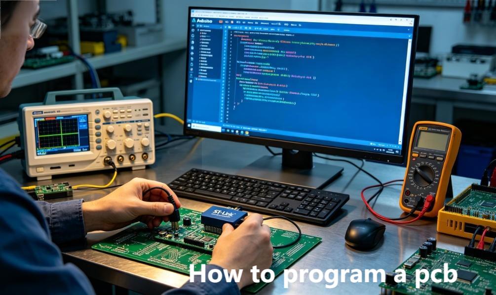
Programming a printed circuit board is the process of loading firmware and embedded software onto onboard microcontrollers, FPGAs, and memory chips to activate full hardware functionality. This complete guide breaks down how to program a PCB with practical workflows, essential tools, and industry-proven best practices for both prototyping and mass manufacturing. Learning the proper PCB programming process guarantees stable performance across consumer electronics, industrial automation, automotive systems, and medical device applications.
What Is PCB Programming, and Why Do You Need It?
PCB programming refers to configuring microcontrollers, FPGAs, and integrated circuits on a finished PCB to execute designated tasks such as sensor monitoring, data processing, and device control. Even a perfectly manufactured PCB cannot operate without properly loaded firmware and program code.
Hardware designers rely on early programming validation to confirm firmware and hardware compatibility and avoid costly redesign iterations.
Procurement and supply chain professionals need clear programming specifications to align production schedules and component sourcing plans.
Technical researchers use PCB programming to validate prototype logic and conduct performance testing for new circuit designs.
Which Tools Are Essential for Programming a PCB?
Three core categories of equipment are required for standard PCB programming: dedicated programming hardware, supporting software platforms, and a prepared target PCB assembly. Tool selection depends largely on the microcontroller or FPGA model used on your circuit board.
Common Programmer Devices
| Tool Type | Use Case | Typical Models |
|---|---|---|
| USB Programmer | Prototyping and small-batch production | ST-Link, J-Link, USBasp |
| In-Circuit Programmer (ICP) | Mass production and post-assembly firmware updates | FlashCAT, SVF Programmer |
| Debugger Programmer | Combined programming and real-time fault debugging | OpenOCD, GDB Compatible Debuggers |
Key Software for PCB Programming
- IDE Platforms: Arduino IDE, Keil C51, Xilinx Vivado for code writing and compilation.
- Programming Utilities: OpenOCD, Flash Loader, AVRDUDE for flashing compiled files onto PCBs.
- Design Software: Altium Designer, KiCad for integrating programming headers and test points into initial PCB layout.
How to Program a PCB in 5 Simple Steps (Beginner-Friendly)
PCB programming follows a standardized, repeatable workflow that works for simple and complex circuit designs alike. Anyone new to the process can follow these clear steps to complete programming successfully.
Step 1: Prepare Your PCB and Onboard Components
Verify that your PCB is fitted with a standard JTAG or SWD programming header and that all target microcontrollers are properly soldered.
Inspect the board for short circuits, cold solder joints, or misaligned components before starting any programming operation.
For mass production layouts, reserve dedicated test points to support automated in-circuit programming later.
Step 2: Write and Compile Firmware Code
Use a professional integrated development environment to write program code in C, C++, or VHDL, then compile the project into standard firmware files in HEX, BIN, or SVF format.
Remove unused functions and redundant code to reduce memory occupancy and improve overall board operating efficiency.
Run virtual simulation testing to validate code logic before flashing it onto physical hardware.
Step 3: Connect the Programmer to the PCB Interface
Connect your programming hardware to the PCB’s dedicated programming header using a matched ribbon cable or insulated USB line.
Always match voltage levels between the programmer and the onboard chip to prevent hardware burnout from voltage mismatch.
Secure all cable connections firmly, as loose wiring is one of the most common causes of failed programming attempts.
Step 4: Load Firmware Files Onto the PCB
Launch your programming software, select the compiled firmware file, and initiate the automatic flashing process following the software prompts.
Wait for the system verification process to finish and confirm a successful write operation before disconnecting the device.
For FPGA-based boards, use dedicated bitstream files to configure internal logic units and hardware pathways.
Step 5: Test and Validate the Programmed PCB
Power on the finished PCB and run functional tests to check core features such as indicator light operation, sensor data reading, and signal output stability.
Use debugging tools to locate and fix firmware errors or hardware compatibility issues if malfunctions occur.
Record programming time, success rates, and test results for future project reference and batch production standardization.
What Are the Common PCB Programming Methods?
Different PCB programming methods suit distinct production volumes, design complexities, and project timelines. The three most widely adopted approaches are listed below for easy selection.
1. In-Circuit Programming (ICP)
In-circuit programming writes firmware directly to components after full PCB assembly through reserved headers or test points. It is ideal for medium to large-scale mass production.
It allows remote firmware upgrades and maintenance without disassembling finished products.
It requires customized programming fixtures and slightly increases production cycle time.
2. Offline Programming
Offline programming pre-flashes firmware onto standalone microcontroller chips before they are soldered onto the PCB. This method fits small batches and simple circuit designs perfectly.
It accelerates assembly procedures and eliminates the need for extra programming headers on the PCB layout.
It makes post-assembly firmware updates difficult without desoldering onboard components.
3. Boundary Scan (JTAG)
JTAG boundary scan leverages a universal industry interface to complete programming and deep-level debugging for high-density PCBs equipped with FPGAs and multi-core processors.
It supports comprehensive hardware testing and real-time logic debugging for complex circuit systems.
It requires JTAG-compliant components and involves a moderate learning curve for new users.
How to Avoid Common PCB Programming Mistakes?
Most PCB programming failures stem from avoidable errors in design preparation, tool configuration, firmware setup, and operational procedures. Below are frequent issues and practical solutions.
Design-Related Mistakes
- Missing reserved programming headers: Always add a standard SWD or JTAG header in the initial PCB layout to support prototyping and debugging.
- Incorrect voltage design: Strictly align programmer output voltage with MCU operating voltage to avoid component damage.
Tool and Firmware Mistakes
- Corrupted firmware files: Recompile source code and verify file checksums before starting the flashing process.
- Outdated software versions: Keep programming tools and IDE platforms updated to support the latest microcontroller and FPGA models.
Process Mistakes
- Unstable physical connections: Use shielded cables and fixed interfaces to reduce signal interference and connection failure.
- Skipping post-programming verification: Always complete functional testing to confirm the PCB runs as expected after programming.
PCB Programming for 4 High-Demand Industries (Real-World Cases)
PCB programming standards and functional targets vary greatly across industries, with each sector requiring customized reliability, power consumption, and compliance performance. Below are four mainstream application fields with detailed practical cases.
1. Consumer Electronics
Applicable products include smart wearable devices, household smart appliances, and portable electronic gadgets.
Adopted PCB type: High-density interconnect multilayer boards built with ESP32 and STM32 low-power microcontrollers.
Core programming targets enable stable Bluetooth and Wi-Fi connection control while maintaining ultra-low power consumption.
This solution solves the dual demand of compact circuit layout and long battery life for portable consumer devices.
2. Industrial Control and Automation
Applicable products cover PLC controllers, industrial sensor modules, and automated production line control boards.
Adopted PCB type: Thick-copper multilayer PCBs with industrial-grade anti-interference design and FPGA chips.
Core programming targets realize real-time data collection, equipment linkage control, and stable operation in harsh working environments.
This solution improves system stability and anti-interference ability for factory automation scenarios.
3. Automotive Electronics
Applicable products include vehicle ECU modules, ADAS auxiliary systems, and in-vehicle infotainment equipment.
Adopted PCB type: Rigid-flex PCBs using AEC-Q100 qualified automotive-grade microcontrollers.
Core programming targets complete engine logic control, safety collision detection, and multimedia system operation.
This solution meets strict automotive safety standards and high-temperature environmental adaptability requirements.
4. Medical Electronics
Applicable products involve physiological monitoring devices, diagnostic testing equipment, and wearable medical monitors.
Adopted PCB type: High-reliability low-noise PCBs with precise signal processing circuits.
Core programming targets accurately collect and analyze human physiological data and ensure stable long-term operation.
This solution complies with medical industry safety regulations and high-precision signal output standards.
FAQ: Common Questions About How to Program a PCB
Q1: Do I need professional software to program a PCB?
A1: Yes. You need an integrated development environment for code writing and compilation, plus dedicated flashing software to load firmware onto the board. Many reliable free tools are available for beginner use.
Q2: Can I program a PCB without a dedicated programmer device?
A2: Simple single-chip designs can use direct USB connection and IDE software for basic programming. Complex FPGA and high-density circuit boards require professional programmer hardware for stable flashing and debugging.
Q3: How long does standard PCB programming take?
A3: Single prototype programming usually takes 5 to 10 minutes. Automated batch programming for mass production can finish thousands of units within a few hours with professional fixtures.
Q4: Is it possible to reprogram a PCB after full assembly?
A4: Yes, if the PCB is designed with reserved ICP or JTAG interfaces. Boards using offline pre-programmed chips are difficult to reflash without component desoldering.
Q5: What is the difference between PCB programming and microcontroller programming?
A5: Microcontroller programming only writes code to a single chip. PCB programming considers overall circuit matching, peripheral component coordination, and system-level functional debugging of the entire board.
Q6: How to guarantee long-term reliability of a programmed PCB?
A6: Complete code simulation before physical flashing, use certified programming equipment, run full functional tests after programming, and follow industry standard specifications for design and production.
How to Integrate Programming Into Your PCB Design Workflow?
Incorporating programming requirements in the early design stage effectively avoids layout defects, production delays, and repeated design modifications in the later phase.
Step 1: Confirm Programming Requirements Upfront
Define microcontroller models, adopted programming interfaces, and voltage parameters in the initial design specification document.
Coordinate with component sourcing teams to select chips that match your chosen programming method and production plan.
Step 2: Add Programming Interfaces in PCB Layout
Place JTAG and SWD headers close to the target chip with short trace routes to reduce signal noise interference.
Layout reserved test points to support automated batch programming and later fault detection.
Reserve physical space for programming fixtures during structural enclosure design.
Step 3: Complete Programming Verification During Prototyping
Program the first prototype sample and verify all preset functions one by one.
Resolve firmware and hardware compatibility conflicts before launching formal mass production.
Document detailed programming steps and parameter settings for manufacturing team reference.
What Core Skills Do You Need to Master PCB Programming?
Professional PCB programming requires a combination of hardware knowledge, software coding ability, and practical problem-solving experience.
Master basic PCB layout principles, microcontroller parameter specifications, and conventional circuit fault diagnosis methods.
Grasp mainstream programming languages and be proficient in operating IDE platforms and flashing tool software.
Develop the ability to troubleshoot firmware errors, connection failures, and hardware matching conflicts.
Learn industry compliance standards to meet certification requirements for different application fields.
How to Choose a Trusted PCB Programming Service Provider?
Outsourcing PCB programming to a professional supplier saves development time and ensures consistent quality for complex designs and large batch orders.
Choose a provider with rich experience working with mainstream MCU and FPGA models across multiple industries.
Confirm they support in-circuit, offline, and JTAG programming methods with automated batch production capacity.
Verify strict quality control processes including post-programming functional testing and complete technical documentation.
We support customized project demands and offer free DFM reports to optimize your design for manufacturing and programming feasibility.
Ready to Program Your PCB? Partner With Thindry for Professional Support
Understanding how to program a PCB thoroughly is essential to turning circuit design drafts into fully functional electronic products. A standardized workflow, proper tool selection, and professional technical support determine the success of prototyping and mass production.
Thindry delivers reliable PCB programming services customized to fit different industry demands and design specifications. We support a full range of microcontroller and FPGA models, serving consumer electronics, industrial automation, automotive, and medical device projects with stable and consistent quality. We support customized project demands and offer free DFM reports to optimize your entire PCB development process.
If you need reliable support for your PCB programming and manufacturing projects, feel free to contact us at sales@pcbtry.com to discuss your requirements and place your order.
0 Comments