
Introduction
Printed Circuit Board (PCB) materials form the foundational building blocks of modern electronics, serving as the substrate that mechanically supports and electrically connects electronic components. These materials determine the performance, reliability, and cost-effectiveness of virtually all electronic devices, from consumer electronics to advanced aerospace systems. The selection of appropriate PCB materials impacts critical parameters including signal integrity, thermal management, power handling capabilities, and operational lifespan of electronic products. With the continuous advancement of electronic technologies toward higher frequencies, greater power densities, and more compact form factors, the role of PCB materials has become increasingly crucial in enabling next-generation electronic applications .
The importance of PCB materials extends beyond basic functionality to encompass reliability, manufacturing yield, and total cost of ownership. Different applications demand specific material properties—consumer electronics prioritize cost-effectiveness, aerospace and automotive applications require extreme environmental stability, while high-frequency communications need controlled dielectric properties. Understanding the characteristics, advantages, and limitations of various PCB materials enables designers to make informed decisions that balance performance requirements with economic considerations. This guide provides a comprehensive overview of PCB materials, addressing key questions and considerations for optimal material selection in diverse electronic applications .
1 What Materials Are PCBs Made Of?
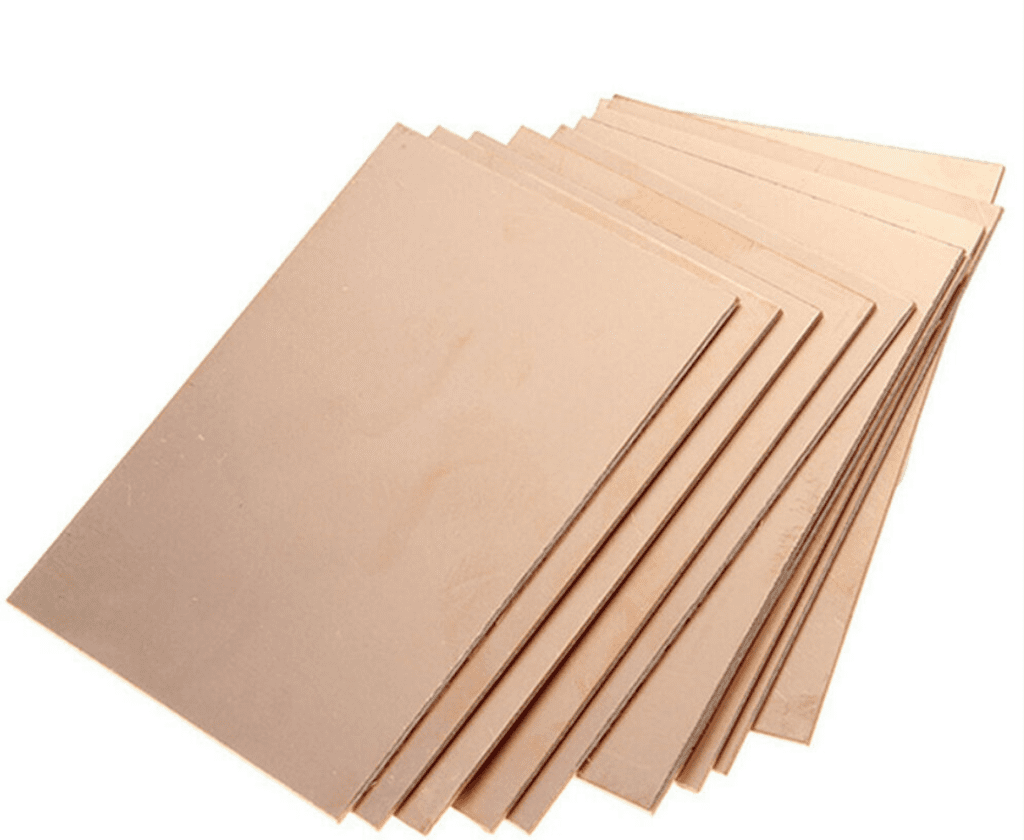
Printed circuit boards consist of multiple material layers that work together to provide mechanical support, electrical connectivity, and environmental protection. The core component is the substrate material, which serves as the insulating foundation. The most common substrate is FR-4, a composite material composed of woven fiberglass cloth impregnated with an epoxy resin that offers excellent mechanical strength and electrical insulation properties. This substrate is clad with a thin layer of electrolytic copper foil (typically 0.5-3 oz per square foot) that forms the conductive pathways through a patterning process. The copper layers are covered with a solder mask (usually a liquid photoimageable polymer) that protects against oxidation and prevents solder bridges, while a silkscreen layer (typically epoxy-based ink) adds component identifiers and logos .
-1024x598.png)
The specific combination of materials varies significantly based on the PCB type and application requirements. Rigid PCBs, which represent the majority of circuit boards produced, predominantly use FR-4 or similar glass-reinforced epoxy laminates. Flexible circuits employ polyimide or polyester films that can withstand repeated bending, while ceramic substrates (such as alumina or aluminum nitride) are used in high-power applications requiring superior thermal conductivity. The conductive elements primarily use copper due to its excellent electrical conductivity (5.96×10⁷ S/m) and relatively low cost, though specialized applications may incorporate silver or gold for specific performance characteristics. Additional materials include prepreg (pre-impregnated fiberglass with partially cured resin) that bonds layers together in multilayer boards, and various surface finishes such as Electroless Nickel Immersion Gold (ENIG), Hot Air Solder Leveling (HASL), and Immersion Silver that protect copper pads and enhance solderability .
Table: Primary Materials Used in PCB Construction
| Material Type | Common Varieties | Key Properties | Typical Applications |
|---|---|---|---|
| Substrate Materials | FR-4, Polyimide, Ceramic, PTFE | Dielectric constant, thermal stability, mechanical strength | All PCB types |
| Conductive Materials | Electrolytic copper, Rolled annealed copper | Conductivity (5.96×10⁷ S/m for copper), thickness | Traces, planes, interconnects |
| Insulating Materials | Prepreg, Solder mask, Coverlay | Dielectric strength, thermal resistance | Layer separation, protection |
| Specialty Materials | High-frequency laminates, Thermal interface materials | Controlled Dk/Df, thermal conductivity | RF/microwave, high-power applications |
Advanced PCB constructions incorporate specialized materials to address specific performance challenges. High-frequency applications utilize materials with controlled dielectric properties, such as PTFE-based substrates (e.g., Rogers RO4000 series) with stable dielectric constants and low loss tangents. Thermal management applications often incorporate metal cores (typically aluminum) or ceramic-filled dielectrics that provide superior heat dissipation. The continuous innovation in PCB materials enables increasingly sophisticated electronic devices, with material scientists developing nano-composites and other advanced formulations to meet the evolving demands of modern electronics .
2 How to Select PCB Materials?
Selecting appropriate PCB materials requires a systematic approach that balances electrical, thermal, mechanical, and economic considerations against the specific requirements of the target application. The process begins with a thorough analysis of the operating environment, including temperature extremes, humidity exposure, mechanical stress factors, and chemical compatibility requirements. For instance, automotive electronics demand materials with high glass transition temperatures (Tg > 170°C) and excellent thermal cycling resistance, while consumer electronics can utilize standard FR-4 materials with lower thermal specifications but significantly reduced cost .
Electrical performance requirements fundamentally influence material selection decisions. For high-speed digital applications, materials with stable dielectric constants (Dk) and low dissipation factors (Df) across the operating frequency range are essential to maintain signal integrity. The dielectric constant affects signal propagation speed and impedance control, while the dissipation factor determines signal loss characteristics. For example, RF and microwave circuits operating above 1 GHz typically require specialized materials like PTFE-ceramic composites (Df < 0.002) rather than standard FR-4 (Df ≈ 0.02) to minimize signal attenuation. Similarly, thermal management needs dictate material choices based on thermal conductivity requirements, with high-power applications often necessitating metal-clad or ceramic-based substrates rather than conventional laminates .
Table: Key Considerations for PCB Material Selection
| Consideration Category | Key Parameters | High-Performance Requirements | Cost-Sensitive Applications |
|---|---|---|---|
| Electrical Performance | Dk, Df, insulation resistance | Low-loss materials (Df < 0.005) | Standard FR-4 (Df ≈ 0.02) |
| Thermal Management | Tg, Td, thermal conductivity | High Tg (>170°C), high thermal conductivity | Standard Tg (130-140°C) |
| Mechanical Requirements | Flexural strength, CTE | High reliability, matched CTE | Standard mechanical properties |
| Environmental Stability | Moisture absorption, chemical resistance | Low absorption, high resistance | Standard environmental protection |
| Manufacturing Factors | Process compatibility, availability | Wide process window, readily available | Standard materials, easy processing |
The manufacturing process compatibility represents another critical selection criterion. Materials must be suitable for the intended fabrication processes, including lamination cycles, drilling characteristics, and compatibility with surface finishes. For instance, polyimide materials withstand higher processing temperatures than standard FR-4 but may require specialized drilling parameters due to their increased toughness. The total cost of ownership encompasses not only the raw material expense but also processing costs, yield implications, and long-term reliability considerations. Designers must balance performance requirements against budget constraints, often making trade-offs between ideal electrical properties and economic practicality. Prototyping with candidate materials provides valuable performance data before finalizing selection decisions, while consultation with material suppliers and manufacturers helps identify optimal solutions based on current industry capabilities and emerging material technologies .
3 What Dielectric Materials Are Used in PCBs?
Dielectric materials serve as the insulating foundation of printed circuit boards, preventing electrical short circuits while providing mechanical support for conductive traces. The most prevalent dielectric material is FR-4, a composite of woven fiberglass cloth impregnated with an epoxy resin that offers a balanced combination of electrical insulation, mechanical strength, and cost-effectiveness. FR-4 exhibits a dielectric constant of approximately 4.5 at 1 MHz, with a dissipation factor of 0.025, making it suitable for most digital and low-frequency analog applications. Its glass transition temperature (Tg) typically ranges from 130°C to 140°C for standard varieties, while high-Tg formulations withstand temperatures up to 180°C, enhancing thermal reliability for demanding applications .
For high-frequency applications, specialized dielectric materials with superior electrical properties are essential. Polytetrafluoroethylene (PTFE)-based substrates, such as Rogers RT/duroid series, provide exceptionally low dissipation factors (as low as 0.0002) and stable dielectric constants across wide frequency ranges, making them ideal for microwave and millimeter-wave circuits. Ceramic-filled PTFE composites offer improved mechanical stability while maintaining excellent high-frequency performance, with dielectric constants tailored for specific impedance requirements (typically 2.5-3.5). Hydrocarbon-based laminates with ceramic fillers provide a balance of electrical performance and manufacturability, often serving as cost-effective alternatives to pure PTFE materials in commercial wireless applications .
Polyimide dielectrics excel in flexible circuit applications and high-temperature environments, offering continuous operating temperatures up to 250°C and exceptional chemical resistance. While their dielectric constant (approximately 3.5) and dissipation factor (around 0.002) suit many high-frequency applications, their primary advantage lies in thermal stability and mechanical flexibility. For the most demanding thermal management applications, ceramic substrates (such as alumina and aluminum nitride) provide exceptional thermal conductivity (up to 25 W/mK for AlN) alongside excellent electrical insulation properties. These materials enable direct mounting of high-power devices while efficiently dissipating heat, though their brittleness and higher cost limit them to specialized applications .
The selection of dielectric materials involves careful consideration of multiple interdependent properties. The coefficient of thermal expansion (CTE) must be compatible with attached components to prevent solder joint failure during temperature cycling. Moisture absorption affects both electrical properties and long-term reliability, particularly in humid environments. Thermal conductivity determines heat dissipation capability, critical for power electronics. Modern PCB designs often employ hybrid constructions combining different dielectric materials to optimize performance in specific circuit regions while managing overall cost. This approach allows designers to place critical high-frequency components on specialized low-loss materials while using standard FR-4 for supporting circuitry, achieving an optimal balance of performance and economics .
4 How Are PCB Material Prepregs Made?
PCB prepreg (pre-impregnated) materials serve as the bonding layers in multilayer circuit boards, consisting of reinforcing fibers pre-impregnated with a partially cured resin system. The manufacturing process begins with fiberglass weaving, where continuous filaments of E-glass are woven into thin fabrics of specific thicknesses and styles. The woven fiberglass then undergoes a resin impregnation process, where it passes through a bath containing precisely formulated epoxy resin with catalysts, hardeners, and flame retardants. The resin viscosity, temperature, and impregnation speed are carefully controlled to ensure complete fiber wetting and consistent resin content throughout the material .
Following impregnation, the prepreg enters a B-staging oven where controlled heat application initiates the polymerization process, advancing the resin to a partially cured state. This B-staging creates a non-tacky, handleable material that remains fusible when heated, allowing for flow and bonding during the final lamination process. The degree of cure, typically ranging from 30% to 60%, critically affects the prepreg’s flow characteristics and final properties. After B-staging, the material is cooled, covered with protective films, and rolled for shipment. The entire process occurs in cleanroom conditions to prevent contamination that could compromise dielectric strength or cause electrical defects in the finished PCB .
The composition of prepregs varies significantly based on the intended application. Standard FR-4 prepregs use brominated epoxy resins for flame retardancy, while high-performance formulations may incorporate polyimide, BT-epoxy, or cyanate ester resins for enhanced thermal or electrical properties. The reinforcement also varies, with standard applications using E-glass, while high-frequency designs may employ specialized low-Dk glass or non-woven reinforcements. The ratio of resin to glass, known as the resin content, typically ranges from 40% to 60%, directly influencing the final dielectric thickness, flow characteristics, and filled via reliability. Prepregs are classified by their glass style (106, 1080, 2116, etc.), which determines the thickness and resin content available for specific layer count and impedance control requirements .
During PCB fabrication, prepregs perform multiple critical functions. They act as adhesive layers bonding core materials together, serve as dielectric separators between copper layers, and fill the gaps in etched circuit patterns to provide a uniform surface. When subjected to the heat and pressure of lamination (typically 180-220°C at 200-500 psi for 60-120 minutes), the resin reflows, completely wetting the adjacent layers before fully curing to form a solid, insulating matrix. The selection of appropriate prepregs requires matching their flow characteristics, gel time, and final cured properties with the specific board construction requirements. Modern multilayer boards often employ mixed prepreg builds combining different glass styles and resin contents to optimize both fill capability and dielectric spacing for impedance control .
5 What Is FR-4 Material in PCBs?
FR-4 (Flame Retardant 4) represents the industry standard substrate material for rigid printed circuit boards, consisting of a composite structure with woven fiberglass reinforcement embedded in an epoxy resin matrix. The “4” designation distinguishes this material from other flame-retardant grades, with FR-4 specifically indicating a brominated epoxy resin system that provides self-extinguishing properties. The material’s popularity stems from its balanced performance characteristics, including a dielectric constant of approximately 4.5 at 1 MHz, a dissipation factor of 0.025, and a glass transition temperature typically ranging from 130°C to 140°C for standard formulations. These properties make FR-4 suitable for the vast majority of commercial and industrial electronic applications .
The manufacturing process for FR-4 begins with the production of glass fabric, where continuous filaments of E-glass are woven into thin sheets of specific thicknesses and styles. This glass fabric then undergoes impregnation with an epoxy resin solution containing bromine-based flame retardants, catalysts, and other additives that determine the final material properties. The impregnated material passes through heating zones that partially cure the resin, creating prepreg sheets that are subsequently laminated with copper foil under heat and pressure to form the final copper-clad laminate. Variations in the resin formulation, glass style, and curing parameters produce FR-4 materials with different characteristics tailored to specific application requirements .
Table: Properties of FR-4 Variants
| Property | Standard FR-4 | High Tg FR-4 | Halogen-Free FR-4 |
|---|---|---|---|
| Glass Transition Temperature (Tg) | 130-140°C | 170-180°C | 130-150°C |
| Decomposition Temperature (Td) | >300°C | >325°C | >310°C |
| Dielectric Constant (1 MHz) | 4.5-4.8 | 4.5-4.8 | 4.4-4.7 |
| Dissipation Factor (1 MHz) | 0.025 | 0.022 | 0.023 |
| Thermal Conductivity (W/m·K) | 0.3 | 0.4 | 0.3 |
| Moisture Absorption (%) | 0.15 | 0.12 | 0.18 |
Several FR-4 variants address specific application requirements. High Tg FR-4 formulations incorporate multi-functional epoxies or phenolic hardeners that raise the glass transition temperature to 170°C or higher, enhancing thermal reliability for lead-free assembly processes and high-power applications. Halogen-free FR-4 materials replace brominated flame retardants with phosphorus or nitrogen-based compounds to meet environmental regulations such as RoHS, while maintaining similar electrical and mechanical properties. Low-loss FR-4 formulations use specialized resins or different glass types to reduce the dissipation factor to approximately 0.015, improving signal integrity for digital applications with data rates up to 5 Gbps. The continuous evolution of FR-4 materials ensures their relevance even as performance requirements escalate, with manufacturers regularly introducing enhanced formulations that push the boundaries of this versatile material family .
Despite the development of numerous specialized materials, FR-4 maintains its dominance in the PCB industry due to its exceptional balance of properties, well-established supply chain, and cost-effectiveness. The material provides sufficient electrical insulation for most applications, with a dielectric strength typically exceeding 1000 V/mil. Its mechanical properties, including flexural strength greater than 400 MPa and good dimensional stability, enable reliable performance in diverse operating environments. The extensive industry experience with FR-4 processing has resulted in optimized manufacturing parameters and troubleshooting knowledge, contributing to high production yields. While specialized materials address specific high-frequency, high-temperature, or other demanding applications, FR-4 continues to serve approximately 80% of the global PCB market due to its versatility and continuous performance improvements .
6 Why Is FR-4 a Popular PCB Material?
FR-4 maintains its dominant position in the PCB industry primarily due to its exceptional balance of properties that meet the requirements of most electronic applications at a reasonable cost. The material offers a dielectric constant of approximately 4.5 at 1 MHz, which provides sufficient electrical insulation for the majority of digital and analog circuits, alongside mechanical properties including flexural strength exceeding 400 MPa that ensures structural integrity under normal operating conditions. Its thermal performance, with a glass transition temperature of 130-140°C for standard formulations, adequately withstands typical soldering processes and operating temperatures. This balanced property profile means that FR-4 performs satisfactorily across electrical, thermal, and mechanical domains without excelling in any single area, creating an optimal compromise for the broad electronics market .
The well-established manufacturing infrastructure for FR-4 represents another significant advantage, with global supply chains ensuring competitive pricing and reliable availability. The material has been manufactured for decades, resulting in refined production processes that deliver consistent quality and properties. This manufacturing maturity translates to predictable processing characteristics during PCB fabrication, including controlled etch rates, reliable drilling performance, and consistent lamination behavior. The extensive industry experience with FR-4 has generated comprehensive troubleshooting knowledge and established best practices that maximize production yields. Additionally, the material compatibility with standard PCB manufacturing processes—such as solder mask application, surface finishing, and assembly operations—reduces implementation risks and simplifies the transition from design to production .
Cost-effectiveness remains a decisive factor in FR-4’s popularity, with the material typically costing 30-70% less than specialized high-frequency or high-performance alternatives. This economic advantage stems from both the mature manufacturing processes and the economies of scale achieved through decades of high-volume production. The total cost benefits extend beyond the raw material price to include lower processing costs, as FR-4 utilizes standard parameters for drilling, routing, and plating operations without requiring specialized equipment or consumables. For the majority of consumer, industrial, and even some automotive applications, FR-4 provides adequate performance at the lowest total cost, enabling competitive product pricing while maintaining sufficient reliability for the intended application lifespan .
The continuous evolution of FR-4 formulations has allowed the material to maintain relevance despite increasing performance demands. Manufacturers have developed enhanced variants that address specific limitations while retaining the fundamental advantages of the FR-4 system. High-Tg FR-4 grades withstand lead-free assembly temperatures, while low-loss formulations improve signal integrity for faster digital circuits. Halogen-free versions meet environmental regulations, and specialized composites offer improved thermal conductivity for better heat dissipation. This adaptability has prevented FR-4 from becoming obsolete, instead allowing it to evolve alongside technological requirements. While specialized materials address niche applications with extreme performance demands, FR-4 continues to serve the broad center of the electronics market where balanced performance and cost efficiency determine material selection .
7 Are FR-1 and FR-2 Used as Materials in PCBs?
FR-1 and FR-2 represent phenolic-based laminate materials primarily used in single-sided printed circuit boards for cost-sensitive applications. Both materials belong to the paper-based composite category, utilizing cellulose paper impregnated with phenolic resin rather than the fiberglass reinforcement found in FR-4. The key distinction between FR-1 and FR-2 lies in their thermal properties, specifically the glass transition temperature—FR-1 offers a higher Tg (approximately 130°C) compared to FR-2 (approximately 105°C), providing better thermal resistance during soldering operations and in elevated temperature environments. This thermal performance difference makes FR-1 more suitable for applications requiring slightly higher reliability, while FR-2 serves the most cost-sensitive applications where thermal demands are minimal .
These materials find their primary application in single-sided consumer electronics where ultra-low cost outweighs performance requirements. Typical implementations include television remote controls, simple power supplies, LED lighting circuits, and basic electronic toys. The manufacturing process for FR-1/FR-2 boards utilizes die punching rather than mechanical drilling, enabling high-volume production at significantly lower costs than possible with FR-4. This approach suits the simple circuitry typically implemented on these materials, with component counts and trace densities far below those of more complex multilayer boards. The inherent limitations of paper-based substrates restrict their use to single-layer designs, as the material lacks the dimensional stability and mechanical strength required for plated through-holes or complex multilayer constructions .
The electrical properties of FR-1 and FR-2 differ substantially from fiberglass-based materials, with higher and less stable dielectric constants (approximately 5.0 at 1 MHz) and greater dissipation factors (approximately 0.03). These characteristics limit their usefulness to low-frequency applications generally below 100 MHz, as signal loss increases significantly at higher frequencies. The moisture absorption of paper-based materials (typically 0.5-1.0%) exceeds that of FR-4, necessitating protective conformal coatings in humid environments. Mechanically, these materials exhibit lower flexural strength and impact resistance, making them unsuitable for applications subject to vibration or mechanical stress. However, for stationary consumer products with simple circuitry, these limitations present acceptable trade-offs against the significant cost savings .
Despite their performance limitations, FR-1 and FR-2 maintain niche applications where cost sensitivity outweighs technical requirements. The materials have evolved to meet modern environmental standards, with halogen-free formulations available that comply with RoHS directives. Some manufacturers offer water-resistant variants with improved moisture resistance, while high-CTI versions provide better tracking resistance for applications with closer spacing between high-voltage conductors. While their market share has gradually declined with the decreasing cost of FR-4 and the trend toward more complex electronics, these materials continue to serve specific market segments where minimizing cost is the primary design consideration. Their ongoing availability demonstrates how even technically inferior materials can maintain relevance when they address specific economic constraints effectively .
Summary
PCB materials constitute a critical element in electronic design and manufacturing, with material selection profoundly influencing the performance, reliability, and cost structure of the final product. The diverse material ecosystem ranges from cost-effective options like FR-1 and FR-2 for simple consumer applications to sophisticated high-frequency laminates and specialized thermal management materials for demanding implementations. FR-4 maintains its position as the industry workhorse due to its balanced properties, established supply chain, and continuous evolution through enhanced formulations that address emerging requirements. This versatility ensures that material options exist for virtually every application scenario, though optimal selection requires careful consideration of electrical, thermal, mechanical, and economic factors .
The future of PCB materials will likely focus on developing solutions that address the converging trends of higher speed, increased power density, and more stringent environmental requirements. Advanced composite materials incorporating nanoscale fillers promise improved thermal and electrical properties, while environmentally conscious formulations reduce the ecological impact of electronic products. The growing integration of electronics into challenging environments—from automotive under-hood applications to miniaturized wearable devices—will drive material innovation toward higher temperature capabilities, greater reliability, and enhanced flexibility. As electronic technology continues to advance, PCB materials will remain a fundamental enabler, with material scientists and engineers collaborating to develop the substrate technologies that will support future electronic innovations .


0 Comments