




FR4 substrate material is a flame-retardant, glass-reinforced epoxy laminate used as the insulating structure of many rigid PCBs. The glass reinforcement supports the board, the cured resin binds and insulates it, and separate copper conductors carry current. FR4 is a material class, not one product with a universal temperature limit or dielectric constant.
That distinction matters when deciding whether a board can carry a fast signal, survive assembly or operate near a heat source. A drawing that says “FR4” identifies a starting point. It does not, by itself, establish the performance of the finished circuit. Here is how to understand the material without mistaking a useful general description for a complete design specification.
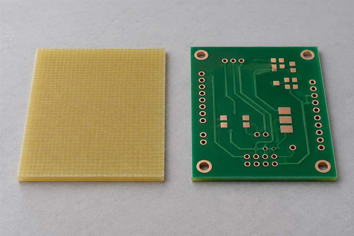
What FR4 Is Made Of and What It Does
FR4 combines glass reinforcement with a cured epoxy resin system. Think of the glass as reinforcement and the resin as the binding, insulating matrix. Together they form a composite rather than a solid block of pure resin or glass.
In a PCB, this composite supports copper features and separates conductors that must remain electrically isolated. The copper is not the FR4, and the green coating commonly seen on a finished board is usually solder mask, not the substrate itself.
| Part | Role | What it does not prove |
|---|---|---|
| Glass reinforcement | Contributes mechanical stability within the resin composite. | That every direction or construction has identical mechanical or electrical behavior. |
| Epoxy resin system | Binds the reinforcement and contributes insulation and thermal behavior. | That all FR4 formulations have the same loss, Tg or moisture response. |
| Copper conductors | Form traces, pads and planes that carry current and distribute signals. | That the entire board is an effective heat sink or meets an impedance target. |
| Solder mask | Provides a patterned coating over selected copper areas. | The underlying laminate grade, its certification or its suitability for a circuit. |
A copper-clad laminate is an insulating sheet supplied with copper bonded to it. A PCB core is a cured laminate used in the construction; prepreg provides partially cured resin and reinforcement for bonding during multilayer lamination. For those manufacturing terms and purchasing details, see the copper-clad laminate specification guide.
The letters FR refer to flame retardance. They should not be read as “cannot burn.” UL explains its flammability classifications as results from specified small-scale tests. A rating concerns defined specimens and conditions; it is not a guarantee that an assembled product cannot ignite or spread fire. Check the recognition applicable to the actual material and construction when it is part of a product requirement.
Why FR4 Does Not Have One Set of Properties
A material family contains different resin formulations and constructions. Use the data for the selected manufacturer’s grade, with its stated conditions, instead of treating an internet table of “FR4 properties” as a purchase specification.
Even within one product family, glass construction and resin content can affect the values relevant to an electrical model. Frequency, direction, conditioning and the test method can also change what a reported number means. A typical value helps describe a material; it does not automatically become a guaranteed lot limit.
For a concrete reference, Isola describes 370HR as a glass-reinforced FR4 epoxy system and reports product-specific values and methods. Its table lists Tg by DSC separately from decomposition temperature and thermal conductivity. That separation is more useful than copying one “maximum temperature” onto every FR4 board.
| Question | Useful evidence | Unreliable shortcut |
|---|---|---|
| What material is this? | Manufacturer, grade, construction and traceability. | Its green color or a generic FR4 label. |
| Will it meet the electrical model? | Relevant dielectric data and a reviewed stack-up. | One Dk value without frequency or method. |
| Will it tolerate the thermal conditions? | Material data plus assembly and operating requirements. | Tg alone. |
| Is a replacement acceptable? | Comparison against design and qualification requirements. | Both products belong to the same family. |
This does not mean every ordinary board needs an elaborate materials investigation. It means the depth of the review should follow the consequence of being wrong. A short, low-speed interconnect and a long, loss-sensitive channel can demand very different evidence even when both boards are described as FR4.
Check Electrical Performance at the Board Level
Electrical insulation, dielectric behavior and controlled impedance answer different questions. FR4 provides an insulating medium, but board geometry, fabrication and operating conditions determine whether the complete design meets its requirements.
Insulation concerns keeping unintended current paths under control. A material’s laboratory electric-strength result is not permission to place any two PCB conductors arbitrarily close together. Conductor spacing, surface conditions, operating voltage and the applicable product requirements still need qualified review. Do not multiply a data-sheet breakdown value by board thickness and call the result a safe working voltage.
Dk, or relative permittivity, describes a dielectric property used in field and transmission-line models. Df, or dissipation factor, describes dielectric loss under stated conditions. Neither alone predicts all signal behavior: conductor geometry, conductor loss, discontinuities and the actual route also contribute.
Controlled impedance is a property of a transmission-line structure, not a yes-or-no label attached to a material family. FR4 constructions can be used for controlled-impedance designs when the selected materials, dimensions and process controls support the requirement. Conversely, buying a specialty laminate does not correct a poorly defined reference plane or an unreviewed stack-up.
Consider two otherwise comparable routes made with the same material: one connects nearby devices, while the other crosses a large board through connectors and vias. The longer path can have a more demanding loss budget. The material name has not changed; the system requirement has. This is why a universal statement such as “FR4 stops working above this frequency” is not a reliable selection rule.
- Identify the actual interface or RF performance requirement.
- Determine which routes and operating conditions are critical.
- Review the proposed material construction, reference planes and geometry with the fabricator.
- Use an appropriate model and agree how the critical performance will be verified.
- If the margin is inadequate, compare a revised construction or material against the same requirement.
Do not confuse an impedance coupon with complete product validation. It provides evidence about the specified test structure; it does not exercise every route, connector or operating mode in the assembled product.
Separate Heat Resistance From Heat Removal
Heat resistance asks whether the material and board can tolerate their thermal exposure. Heat removal asks how heat reaches the surrounding air, chassis or another cooling path. A material improvement in one area does not automatically solve the other.
Tg describes a transition in resin behavior, not a universal continuous operating-temperature rating. Assembly heating is also different from years of service. Review the complete exposure and board construction; use the high-Tg temperature-rating guide for a more detailed explanation of those distinctions.
For heat removal, ask where the heat goes. A component may transfer heat into copper, through vias or interfaces, and onward to an enclosure or heat sink. The glass-epoxy dielectric is only part of this path. Increasing Tg does not add a heat sink, improve airflow or fix a poor thermal interface.
A simplified heat-flow example
For one-dimensional steady conduction through a uniform slab, thermal resistance is R = L / (k × A), where L is thickness in meters, k is conductivity in W/(m·K), and A is area in square meters. Suppose, solely for teaching, that L is 0.001 m, k is 0.4 W/(m·K) and A is 0.0001 m². The calculated slab resistance is 25 K/W.
At 1 W flowing through that idealized slab, the model predicts a 25 K temperature difference across it. It does not predict the component’s operating temperature. Real boards have copper, lateral spreading, contacts and other heat paths, and their conductivity may depend on construction and direction. The example shows why both path length and area matter; it is not a thermal qualification for a particular PCB.
When a hot component is the concern, identify power dissipation, allowable temperatures, ambient conditions and the cooling arrangement. Then assess the board and package together. A metal-backed or ceramic solution may be worth evaluating for a particular heat path, but neither is a universal replacement for FR4 or a guarantee of a cooler product.
Understand Mechanical and Environmental Limits
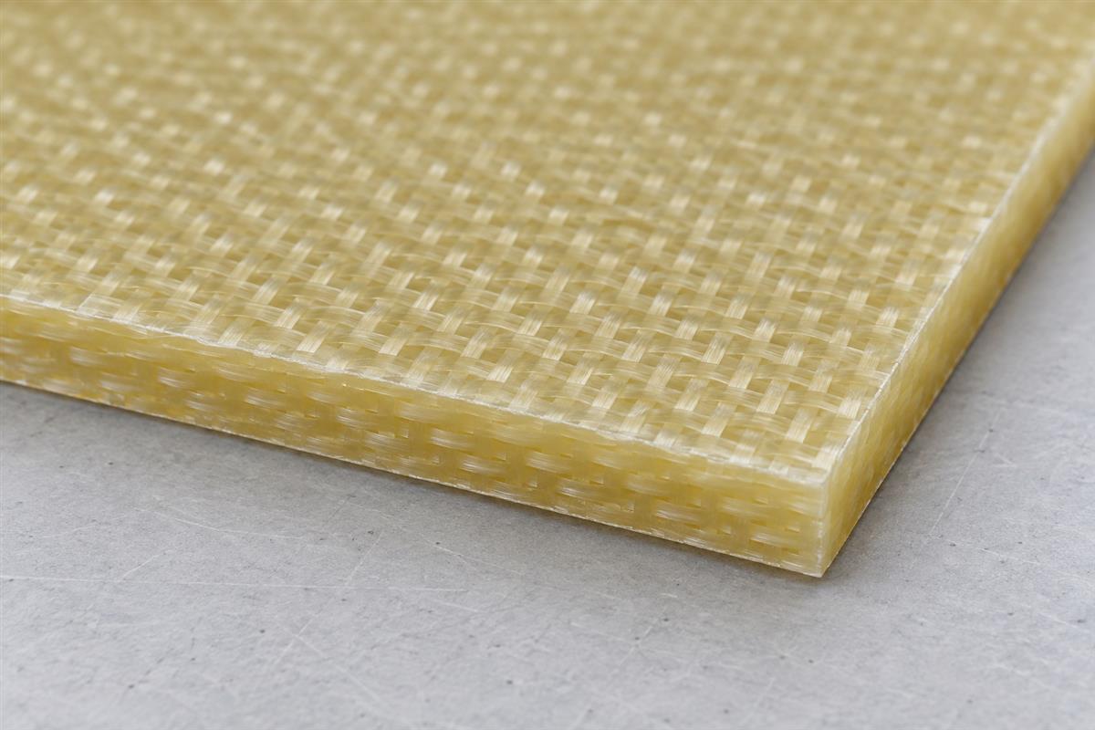
FR4 is generally used as a rigid structural dielectric. Some thin boards can flex, but visible bendability does not establish suitability for repeated bending. Copper, plated holes, solder joints and components can impose limits before the laminate visibly breaks.
Review board support, connector loads, mounting locations, component mass, assembly handling and vibration where relevant. A thicker board is not automatically the correct answer: the geometry and load path matter, and a thickness change can affect fabrication and component fit. Avoid choosing a universal thickness solely because the product is automotive, medical or industrial.
Moisture also needs context. A data-sheet absorption test describes a specimen under defined conditions, not a promise of unchanged behavior in every humid environment. Board contamination, surface spacing, processing and protection can influence the finished product. Assess the actual environment rather than assuming “low moisture absorption” means waterproof.
For example, a controller inside a dry enclosure and a board exposed to condensation do not have the same reliability question. The latter may need a wider review of contamination control, enclosure behavior, protection and validation. Changing the laminate name alone cannot demonstrate that those risks are controlled.
Ask the responsible engineers to identify the relevant acceptance test and failure criterion before approving the material. “Survives harsh environments” is too vague to establish what must be checked.
Decide Whether FR4 Fits the Application
FR4 is a useful candidate when a compatible grade and board construction meet the electrical, thermal, mechanical and qualification requirements. The decision should be requirement-led, not based on a blanket claim that FR4 is always sufficient or always inferior.
| Application concern | First question | When to investigate further |
|---|---|---|
| General rigid control or interface board | Can a supported FR4 construction meet the documented conditions? | Assembly, voltage, environment or qualification requirements remain undefined. |
| Loss-sensitive digital or RF path | Does the modeled and verified channel meet its budget? | Loss, phase or impedance margin is insufficient. |
| Concentrated heat source | Is there an adequate path from the component to the cooling environment? | Temperatures cannot be controlled with the proposed construction. |
| Repeated movement | Is the interconnect designed and qualified for the bend duty? | The design relies on repeatedly bending an ordinary rigid board. |
| Demanding humidity or insulation conditions | Do the material, layout and protection meet the actual exposure? | A generic laminate label is the only supporting evidence. |
Before releasing the choice, record the selected grade, the proposed construction, the critical requirements and the evidence used to close them. Identify what is still an assumption. Ask the fabricator to flag deviations before production rather than silently substituting another material under the same family name.
A useful handoff includes the fabrication drawing, proposed stack-up, relevant electrical targets, assembly and service conditions, mechanical constraints and required qualification. State who approves material changes. For an established product, preserve the approved material and change history so that a later substitution can be evaluated against the same baseline.
FR4 Substrate Questions
Is FR4 the green part of a circuit board?
The visible green coating is usually solder mask. The underlying substrate is a separate material. Color alone cannot identify its grade or properties.
Is FR4 a conductor?
The glass-epoxy substrate is used as an insulator. Copper traces and planes carry current. Insulation still has limits and must be evaluated under the intended conditions.
Does FR4 mean a four-layer board?
No. The material designation does not specify the PCB layer count. FR4-based constructions can be used in different layer counts.
Is all FR4 halogen-free?
No. Do not infer halogen content or environmental compliance from the FR4 name. Obtain the declaration for the selected grade and the requirements applicable to the product.
Can FR4 be used for controlled impedance?
Yes, when the material construction, geometry and process controls support the target. It is the reviewed transmission-line structure and its verification that matter, not the family name alone.
Does higher Tg improve heat dissipation?
Not by itself. Tg concerns resin behavior with temperature. Heat removal depends on the complete thermal path, including copper, interfaces, cooling and geometry.
Can a thin FR4 board replace a flexible circuit?
Not without a design and reliability review. A rigid board that bends once is not automatically suitable for a specified repeated-bending duty.
What should I ask before accepting another FR4 grade?
Ask for the exact product and construction, the differences against critical requirements, any stack-up changes, and the validation or qualification evidence needed for approval.
Need to check a proposed FR4 construction? Send PCBtry your drawing, stack-up and application requirements. Identify the material choices that are fixed and the questions that remain open, then request confirmation of the proposed grade, construction and any deviations before production.



1 Comment
Bare PCB Manufacturing Process: Fabrication Steps, Controls and Final Testing - thindry pcb manufacturer · 09/08/2026 at 09:39
[…] finished thickness interact with impedance, drilling, lamination, and dimensional behavior. This FR-4 substrate explanation helps clarify what the material designation does—and does not—tell a […]