
Most electrical engineers and individuals working with printed circuit boards are familiar with FR4 material. FR4 is the cornerstone of most rigid circuit boards. However, many are unclear about what FR4 actually is, let alone why it has become the most popular PCB substrate material.
What is FR-4?
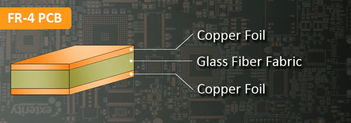
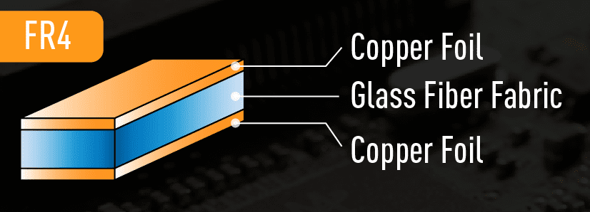
FR-4 is a glass fiber epoxy laminate. The “FR” in FR4 stands for Flame Retardant, meaning that FR-4 boards will not sustain a flame. The number “4” distinguishes it from other materials in its class. FR-4 also denotes the grade used in manufacturing these laminates. The material’s composition complies with the UL94V-0 standard. In single or double-layer PCBs, the FR-4 board acts as an electrical insulator between the top and bottom layers of copper foil; in multilayer PCBs, additional prepreg layers are pressed between the central core and the top and bottom copper layers.
What Are the Properties of FR4 Substrate?
Flame Retardants
Chemicals applied to materials to prevent or delay the spread of fire are known as flame retardants. FR4 substrate offers excellent thermal, mechanical, and electrical properties, making it ideal for various electronic applications.
Flame retardant laminates and prepreg are highly versatile, adaptable to various manufacturing processes, and yield predictable results.
Good Electrical Properties
The electrical characteristics of PCB materials are crucial for signal integrity and impedance. They determine how quickly electrical signals propagate through the material and how much charge the material can retain per unit volume. The table below lists some key electrical properties and their typical values.
| Electrical Property | Typical Value |
|---|---|
| Dielectric Constant (Dk) | 5 @ 1MHz |
| Electrical Strength | 800 to 1800 V/mil |
| Dissipation Factor (Df) | 0.009 @ 1MHz |
| Surface Resistivity (ρS) (Ω/sq) | 10^5 to 10^10 |
Note: Values may vary by manufacturer. For example, the dielectric constant of FR4 ranges between 3.8 and 4.8, depending on the glass weave style, thickness, and resin content.
Low Moisture Absorption
Moisture absorption refers to the ability of PCB material to resist water absorption when immersed. It indicates the percentage increase in weight of the board material due to water uptake under controlled conditions. FR4 material has a moisture absorption rate of only 0.10% after 24 hours of immersion in water.
How is FR-4 Used in PCBs?
These properties make FR4 the ideal default substrate material for high-quality PCB manufacturing processes. When used correctly, these characteristics can also form the foundation of high-quality, low-cost PCBs.
In PCBs, FR4 serves as the primary insulating backbone. It is the base upon which manufacturing companies build circuits. Once prepared, the FR4 board is laminated with one or more layers of copper foil using heat and adhesive. These copper layers form the circuits in the finished product and may cover one or both sides, depending on the board design.
Complex PCBs may utilize multiple sides or even multilayer boards to create more intricate circuits. Prior to this, the circuits are drawn and etched, then covered with a solder mask in preparation for the final silkscreen layer and subsequent soldering processes.
How to Determine FR4 Thickness for PCB Design?
When ordering laminates for a PCB project, the designer or electrical engineer must specify the FR4 thickness. Thickness is measured in inches (e.g., thousandths of an inch or mils) or millimeters, depending on which unit is most suitable for the specific case. FR4 sheets are available in a wide range of thicknesses, depending on project requirements, typically from 10 mils to 3 inches.
Although board thickness may seem insignificant in PCB design, it is actually an essential characteristic. Board thickness affects multiple functionalities, so several factors must be considered when determining it:
Space: Thinner is Better
If designers are concerned about space, they generally prefer thinner FR4 boards. This is crucial for manufacturing small devices, such as USB connectors and many Bluetooth accessories. Even for larger projects, thinner FR4 PCBs are often chosen to save internal space.
Connections: Incorrect Connections Can Cause Damage
Double-sided PCB designs require edge connectors to link both sides. This can be a major limiting factor for the final PCB dimensions, as PCB edge connectors are only compatible with specific thicknesses. The mating part of the connector must fit snugly against the PCB edge; otherwise, it may slip off or damage the PCB. This is one of the main reasons why circuit design takes precedence over material selection.
Impedance Matching: Key to Maintaining Board Functionality
Every multilayer board acts as a capacitor between adjacent layers. Thus, board thickness is critical—the thickness of the PCB FR4 material determines the dielectric thickness, which in turn affects capacitance.
This is particularly crucial for certain high-frequency PCBs, such as RF and microwave designs. High-frequency designs prioritize impedance matching as a vital component for maintaining optimal board functionality, making it essential to achieve the correct capacitance for each layer.
Flexibility: Depends on the Application
Thinner boards can bend to some extent. Although flexibility is an uncommon characteristic, it can be either an advantage or a disadvantage, depending on the application.
In applications where products are frequently subjected to stress or bending, flexible circuit boards are often preferred. For example, PCBs in medical and automotive applications tend to favor flexible boards due to constant pressure and bending.
However, flexibility can adversely affect the PCB manufacturing process, leading to significant issues during assembly. If handled by machines, flexible boards may bend during soldering, causing components to tilt. Additionally, such bending can damage newly installed components and existing connections on the board.
Design Requirements: Intended Use Influences FR4 Thickness
Thinner boards are not always preferable, primarily because they limit PCB design. Thin FR4 boards cannot accommodate grooves and must not be too large, as they are prone to breaking. Thicker boards, on the other hand, can achieve both. This must be considered when weighing different FR4 thicknesses.
Component Compatibility: May Apply to a Small Range
Board thickness also affects the compatibility of components with the board. Like edge connectors, many components are designed for a narrow range of board thicknesses. This is especially true for certain through-hole components.
Weight: Lighter Products May Be More Attractive
Logically, the thickness of FR4 affects the final PCB weight. While weight may not be critical in some applications, it is often a consideration in consumer electronics. Lighter PCBs result in lighter products, reducing shipping costs and, in some cases, being more appealing to consumers.
FR4 Material Properties by Manufacturer
| Manufacturer & Name | Glass Transition Temp (Tg) (°C) | Decomposition Temp (Td) (°C) | Dk @10GHz | Df @10GHz | Moisture Absorption (%) | Application Area |
|---|---|---|---|---|---|---|
| Isola-370HR | 180 | 340 | 3.92 | 0.025 | 0.15 | Normal Speed, Normal Loss |
| Isola-FR408HR | 200 | 360 | 3.65 | 0.0095 | 0.15 | High Speed, Low Loss |
| Nelco-N4000-13 | 210 | 350 | 3.6 | 0.009 | 0.1 | Medium Speed, Low Loss |
| Nelco-N4000-13SI | 210 | 350 | 3.2 | 0.008 | 0.1 | Medium Speed, Low Loss |
| Ventec-VT-47 | 170 | 340 | 4.27 | 0.016 | 0.12 | Normal Speed, Normal Loss |
Limitations of FR4 Circuit Board Material
FR4 material has been used in printed circuit board production for many years. It is inexpensive and offers good electrical insulation. However, when used in high-speed applications, the following issues may arise:
Insulation Stability
Although FR4 is a good insulator, its performance has limitations under high power, high voltage, or high temperature. Beyond certain limits, the material’s insulating properties degrade, and it may begin to conduct electricity. This can lead to board failure.
Controlled Impedance
FR4 does not have a uniform dielectric constant like high-speed board materials. As frequency increases, the dielectric constant (Dk) changes. High-speed materials have a dielectric constant tolerance of less than 2%, while FR4 can have tolerances up to 10%.
The variation in Dk for FR4 material poses challenges in maintaining impedance values. Therefore, it is not the preferred material for controlled impedance boards.
Signal Loss
Signal loss is a critical aspect of PCB design, especially in high-frequency applications. FR4 is not ideal for such applications due to its higher dissipation factor (Df) compared to high-frequency materials.
The Df of FR4 is approximately 0.020, while most high-frequency laminates have a Df of about 0.004—roughly one-fourth that of FR4. A lower Df results in less overall signal loss.
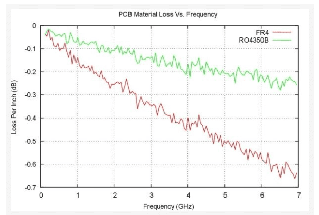
Another drawback is that the Df of FR4 increases with signal frequency, meaning these PCBs experience higher signal loss compared to boards made with high-frequency laminates. The graph above plots frequency versus loss per inch (dB) for FR4 and Rogers RO4350B (a high-speed material). It clearly shows that FR4 material incurs higher losses at high frequencies.
When to Use FR4?
Many electronic applications opt for epoxy-based FR4 circuit boards. Their high strength, reliability, and relatively low cost make FR4 epoxy substrates a logical default choice for electrical engineers. However, FR4 is not suitable for all scenarios, especially in high-frequency designs. For such designs, high-frequency laminates are often the more common choice.
Choosing between these materials can be challenging, which is why we provide a more detailed guide below.
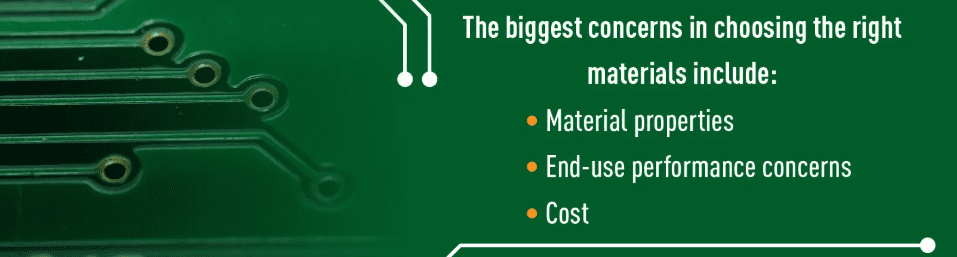
When deciding whether to use FR-4 or high-frequency laminates for PCB construction, consider the following key characteristics of each material:
Cost: FR4 Will Be Cheaper
FR4 material is a very common PCB substrate, primarily due to its relatively low cost. High-frequency laminates are significantly more expensive, which is a major drawback for cost-conscious designers and manufacturers. This is also a key limiting factor when choosing between FR4 and high-frequency laminates.
Signal Loss: Lower Df Reduces Signal Loss
In many cases, signal loss is a critical part of PCB design, especially at high frequencies where it becomes a greater issue. For these designs, FR4 is not ideal—its Df (dissipation factor) is higher than that of high-frequency laminates. This means FR4 circuits will experience greater signal loss compared to identical circuits on high-frequency laminates.
FR4 has a Df of approximately 0.020, while most high-frequency laminates have a Df of about 0.004, only a quarter of FR4’s Df. A lower Df results in less overall signal loss. Another issue is that FR4’s Df increases with signal frequency, meaning signal loss also increases as frequency rises. Due to their more stable Df characteristics, high-frequency laminates exhibit lower losses at higher frequencies.
Impedance Stability: Dk Stability Is Crucial
Stable impedance is another important factor for many designs, as it typically leads to more predictable performance, especially for larger circuits or high-frequency designs. In this regard, FR4 and high-frequency laminates perform differently. Maintaining stable impedance requires the material to maintain a consistent Dk (dielectric constant) across temperature variations and throughout the material.
FR4 is not suitable for maintaining stable impedance because its Dk value can vary significantly within a single board and with changes in board temperature. High-frequency laminates have smaller variations in Dk, remaining largely constant across the board and with temperature changes.
Temperature Management:
Temperature performance is another factor to consider when choosing between FR4 and high-frequency laminates as PCB substrates. When comparing temperature performance, the thermal coefficient of the dielectric constant is a good metric. This value measures how much the material’s dielectric constant changes with temperature:
- For FR4, this value is approximately 200 ppm/°C.
- For high-frequency laminates, it is about 40 ppm/°C.
While both seem small, the results are significantly different. FR4’s larger coefficient means that Dk values can vary widely across the board. In contrast, high-frequency laminates’ lower coefficient means smaller temperature variations across the board. This is particularly important when designing boards for higher temperature environments.
Dielectric Constant: Choosing the Right Dk Value
Sometimes, the dielectric constant of the board is as important as its other characteristics. The board’s dielectric constant affects the size of circuit transmission lines, especially in high-frequency circuit designs like RF or microwave. Smaller transmission lines allow for smaller circuits.
Therefore, if a smaller board size is desired, materials with higher Dk values are the best choice. FR4 has a dielectric constant of about 4.5, which is lower than that of high-frequency materials (typically between 6.15 and 11). Using these high-Dk materials can significantly reduce the final board size by 25% or more.
Operating Environment:
The operating environment of the circuit is another factor to consider when choosing between FR4 and high-frequency laminates. This includes environmental conditions such as humidity and temperature. In both cases, high-frequency laminates offer better resistance to moisture and heat compared to FR4, meaning the impact of the operating environment on circuit functionality is significantly reduced. This is crucial if the PCB needs to operate outdoors or in extreme industrial environments.
In short, high-frequency laminates possess various physical properties, many of which are superior to FR4. The only disadvantage of high-frequency laminates relative to FR4 is their higher cost, which is a significant factor for cost-conscious designers. Therefore, the key is whether the advantages of high-frequency laminates outweigh the cost.
Conclusion
Despite some limitations, FR-4 material strikes a highly effective balance between cost, durability, performance, manufacturability, and electrical properties, making it the most common and popular substrate material.


0 Comments