




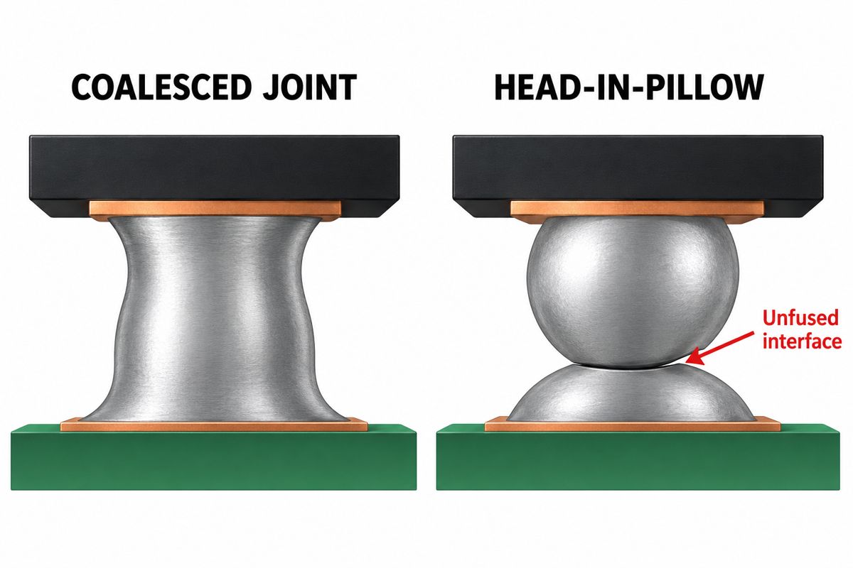
A head-in-pillow solder defect occurs when a BGA solder ball and the reflowed paste on its PCB pad remain separate instead of forming one metallurgical joint. They can touch and sometimes conduct electricity without making a reliable connection. The practical response is to locate the suspect connection, confirm the interface condition, and investigate printing, material condition and the measured thermal process before changing the recipe.
A board that works when pressed is a suspect assembly, not a confirmed HiP diagnosis. Preserve an unreworked sample: reheating can change the evidence you need to distinguish a solder-interface problem from a damaged pad, via or component.
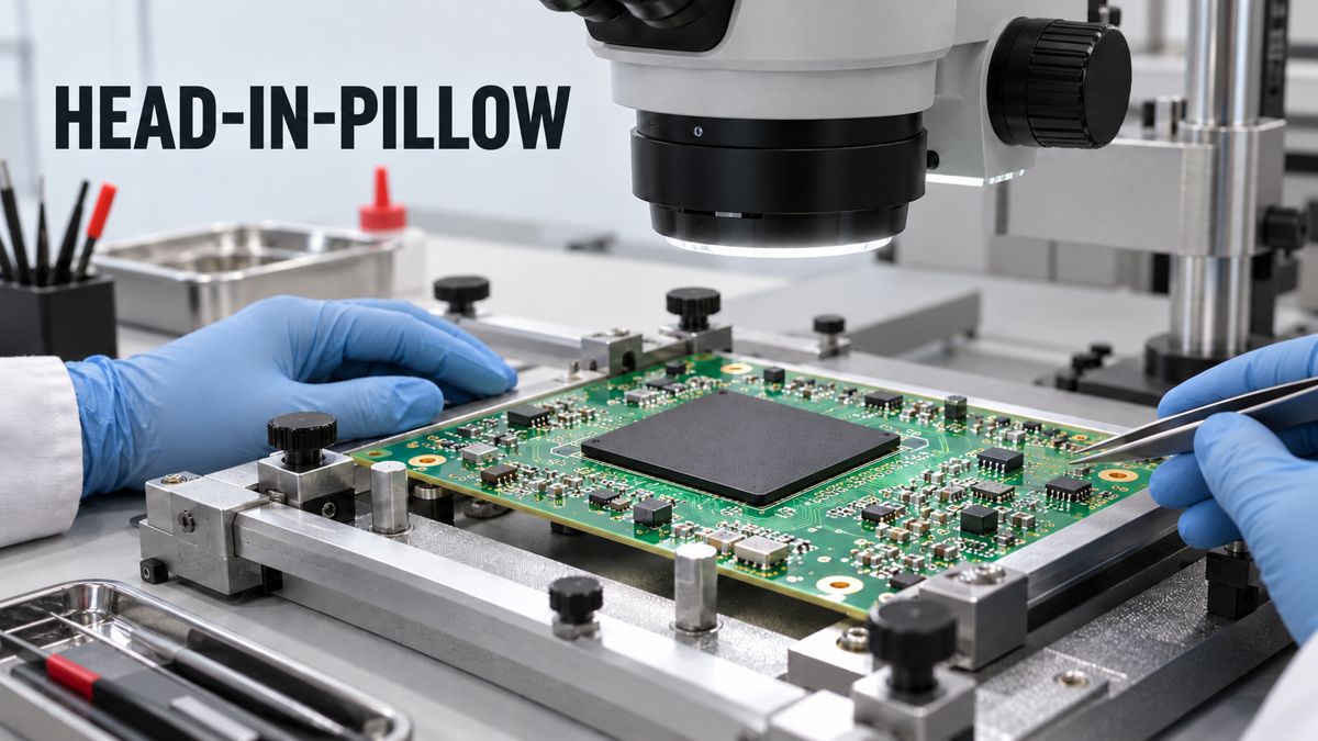
What is a head-in-pillow solder defect?
HiP is a failure to join the package ball to the solder deposited on the board, even though the two shapes may appear to rest against one another. Head-on-pillow and ball-and-socket are names used for the same family of defects.
The important boundary is the ball-to-paste interface. A rounded ball sitting over a rounded deposit is not the same evidence as a continuous joint. AIM’s technical paper explains why electrical contact can coexist with inadequate mechanical strength. Therefore, a successful power-on test does not resolve a suspected interface defect.
Use the term only after the available evidence supports that morphology. Intermittent BGA operation also has other explanations; naming every intermittent connection HiP sends the investigation toward the wrong corrective action.
Head-in-pillow vs cold joints, voids and bridges
Separate the failure mechanism from the symptom before selecting an inspection method or repair.
| Condition | What distinguishes it | What to check next |
|---|---|---|
| Head-in-pillow | Ball and reflowed paste have not coalesced at their interface. | Correlate the failing net with joint-level evidence; investigate contact and wetting conditions. |
| Insufficiently reflowed joint | The relevant solder did not experience a suitable melting and wetting cycle. | Measure the assembly temperature history against the actual alloy, paste and component requirements. |
| Void | A cavity inside solder, rather than necessarily a separated ball-to-paste interface. | Assess location and extent against the applicable product criteria; a void alone does not identify HiP. |
| Bridge | Unwanted solder connection between conductors. | Check electrical shorts and the corresponding image/print geometry. |
| Cracked pad, via or joint | A different separation location can produce similar intermittent behavior. | Ask failure analysis to identify the fracture location, not merely report an open circuit. |
“Cold joint” is often used loosely. In a failure report, replace that label with the observed interface, measured thermal evidence and inspection method. This makes the proposed fix testable.
What causes head-in-pillow in BGA assembly?
HiP develops when the ball and paste cannot form a sound joint during the available contact-and-wetting window.
Package or board distortion can temporarily separate them during heating. Surface oxidation and the remaining activity of the flux then influence whether they join when contact returns. The Research In Motion case study treats the defect as an interaction among materials and process variables, not simply an oven-temperature error.
Room-temperature flatness does not prove that a package stays flat throughout reflow. Published package-warpage research demonstrates that thermal deformation and atmosphere affect the process window. Its measured thresholds belong to the studied assemblies; they are not universal BGA limits.
| Investigation branch | Evidence to collect | Bounded trial |
|---|---|---|
| Print inconsistency | Paste volume, height and position at failed versus sound locations; stencil condition and print sequence. | Restore repeatable deposits first. Any aperture change must also be checked for bridging and release. |
| Thermal contact loss | Failure map, package orientation, board support and temperature-dependent warpage evidence. | Evaluate support or an approved profile adjustment while checking other thermally sensitive parts. |
| Wetting/material condition | Paste identity and age, handling record, ball alloy, component lot and storage history. | Compare controlled material lots or a qualified paste candidate without changing every variable together. |
| Thermal exposure | Recorded assembly profile at representative locations, not only oven zone settings. | Bring the measured profile into the overlapping paste/component/board process window. |
This table is an investigation worksheet, not a list of proven causes for your board. Record a hypothesis and a pass/fail observation for each trial. A correlation with one component lot warrants comparison and supplier review; it does not by itself prove defective components.
How do you detect head-in-pillow defects?
Use electrical localization and joint inspection together; do not clear a suspect assembly from a single top-down image.
- Freeze the evidence. Record board serial number, assembly revision, component reference, failing function and the conditions under which it fails. Segregate suspect units and retain at least one representative unreworked sample when possible.
- Localize the connection. Use the schematic, netlist and available test access to narrow the affected nets. Record which tests cannot exercise the suspected connection. Avoid repeated bending or pressing as a production screening method.
- Request targeted imaging. Provide package orientation and ball coordinates to the inspection operator. Ask what the chosen views can resolve at the interface and what they cannot. A package overview without the failing-ball location is weak evidence.
- Escalate unresolved cases. A qualified failure-analysis team may select angled imaging, three-dimensional examination or destructive analysis such as cross-sectioning/dye-and-pry, according to access and the suspected mechanism. Agree the sample plan before destroying evidence.
- Close the causal loop. Match the observed failure location to the electrical symptom, then compare failed and sound samples from the relevant build conditions.
Indium’s Testing and Prevention of Head-in-Pillow paper notes limited X-ray sensitivity for this defect and describes destructive assessment in its experimental work. That is a reason to document inspection limitations, not a claim that every X-ray system fails or every assembly needs destructive testing.
For the broader distinction between functional coverage and physical inspection, see assembly test methods and coverage gaps.
How can you reduce head-in-pillow on the next build?
Make one evidence-led process change at a time, then verify both joint condition and electrical behavior.
Start by stabilizing the current build: confirm material identity, print consistency and the measured profile. Next, choose the branch supported by the failure evidence. For a suspected wetting limitation, discuss paste chemistry with the supplier. For contact loss, investigate package behavior and support. For insufficient print, correct the print process before using heat as compensation.
Do not assume a higher peak or a longer soak is safer. More thermal exposure can also consume flux activity or change distortion. Conversely, reducing heat without measuring the joint can leave solder inadequately reflowed. Use the actual materials’ requirements and an instrumented assembly; the PCB reflow process guide covers that wider profile-control workflow.
Nitrogen is a possible process-development variable, not a guaranteed fix and not a substitute for adequate contact. Record atmosphere conditions and keep other trial inputs controlled. Select the sample size, inspection coverage and reliability checks for the product’s risk before judging a trial successful.
For existing failed units, obtain an approved rework plan. A temporary recovery after reheating is not evidence that the original cause has been removed. Rework feasibility depends on package, board damage, thermal history and verification access; sometimes replacement or rejection is the defensible choice.
Indium8.9HF parameters: what do they tell you?
Named-product data help define a controlled paste trial, but do not qualify your BGA assembly by themselves.
The following values come from Indium’s official Indium8.9HF product document, Form 99516 R6. They apply to that document’s product and stated conditions, not every solder paste or every member of the 8.9HF family.
| Published item | Value and conditions | Use in a trial |
|---|---|---|
| Stencil life | 60 hours at 22–28°C and 30–60% RH. | Log actual exposure. This is not permission to ignore contamination or uncontrolled shop conditions. |
| Refrigerated storage | 12 months at 0–10°C. | Check the received lot and storage record; obtain current handling instructions. |
| Enhanced SIR requirement | Minimum 500 MΩ; 1,000-hour test; 0.2 mm spacing; 10 V and 50 V; B52/B53 coupon. | An electrical-insulation test condition, not a solder-joint strength or HiP acceptance limit. |
The document does not give tolerance bands for these entries or a universal BGA reflow recipe. Confirm the exact alloy, powder grade and current product data sheet with the supplier. Its HiP-resistance positioning is a reason to evaluate a candidate, not a promise that changing paste eliminates defects. PCBtry is not claiming that this named paste is used on every order.
What should you send for a BGA failure review?
Send a traceable evidence package that connects the symptom, physical location and build history.
- Board revision, serial numbers, quantities tested and the number failing under a defined test.
- BOM, package part number, ball map, component lot/date code and relevant handling records.
- Gerber/ODB++ data, placement file, stencil information and available print measurements.
- Measured profile with thermocouple locations and relevant oven/atmosphere settings.
- Original inspection images with orientation, coordinates, method and any stated resolution limitations.
- Rework history, unreworked sample availability and the required acceptance/reliability criteria.
Keep this checklist with the investigation so a paste change, supplier discussion or repeat build uses the same baseline. For a new assembly project, contact PCBtry with the build files and test requirements to discuss the assembly scope and suitable verification plan. Confirm any specialist failure-analysis or imaging requirement explicitly rather than assuming it is included.
Head-in-pillow FAQ
Does a BGA working only under pressure prove head-in-pillow?
No. It suggests a mechanically sensitive fault but does not locate the separation. Preserve the board and correlate failing nets with physical evidence. A cracked pad, via or other connection can create a similar symptom; pressure is not an acceptable permanent repair.
Can a normal top-down X-ray rule out HiP?
No. A projected image can hide a poorly joined interface behind overlapping solder shapes. Ask the inspection operator whether the suspect interface is actually resolved and whether additional views or failure analysis are needed. “No obvious bridge” is a narrower conclusion than “all joints are sound.”
Can head-in-pillow pass a functional test?
It can. Electrical contact during that test does not establish a strong metallurgical joint or coverage of every connection. Combine the test result with the investigation evidence and the product’s acceptance plan rather than treating one successful startup as proof of reliability.
Could the component lot be responsible?
It is a hypothesis worth investigating when failures correlate with a lot. Compare traceable lots under controlled assembly conditions and review storage and package information with the supplier. Do not attribute the cause to the component until competing print, profile and board explanations have been examined.
Will a hotter reflow profile fix the problem?
Not necessarily. Change the profile only against measured assembly temperatures and the applicable process window. A blanket heat increase can create new damage or worsen other process interactions. First establish whether the evidence points to inadequate heating, contact loss or wetting limitations.
Should I change solder paste for the next build?
A paste trial may be appropriate when wetting or oxidation resistance is implicated. Keep the alloy compatibility, print process and profile requirements explicit. Compare candidate results with the baseline using the same inspection criteria; a different product name is not a corrective-action result.
Should failed boards be reflowed or reballed?
Neither is an automatic choice. Rework requires a diagnosis, damage assessment and approved thermal process. Reballing does not repair a damaged PCB pad or internal component fault. Select the action with a qualified rework provider and verify the completed assembly against the agreed criteria.
Can I build a BGA prototype without access to X-ray?
You can attempt assembly, but inaccessible joints leave verification gaps. Decide whether those gaps are acceptable for a limited prototype, arrange outside inspection when needed, and avoid treating prototype operation as production qualification. The cost of obtaining evidence belongs in the build decision.


0 Comments