




For reflow thermocouple attachment, put the sensing junction in direct thermal contact with the location you need to measure, secure that contact with a qualified method, and relieve the wires separately. A probe hanging above the PCB measures a different thermal environment. Choose the attachment for the available surface and temperature exposure, not just for how easily it sticks.
This guide covers instrumenting a representative profiling assembly. It does not prescribe a universal oven recipe or authorize modifying a saleable board. For the surrounding production stages, see the PCB reflow process guide.
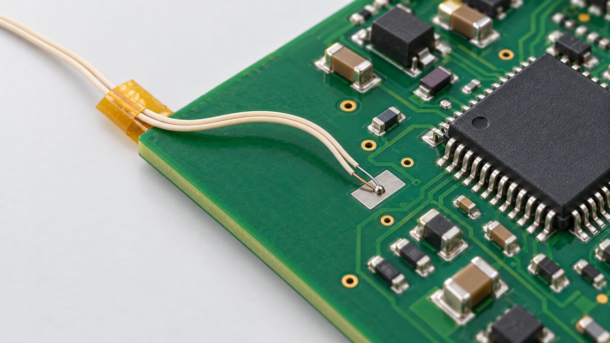
Where should a thermocouple touch the PCB?
Define the measurement before attaching the probe: solder-joint temperature, package-body temperature, board-surface temperature or oven air. Label those channels differently. For an accessible joint, the target is the component termination or pad at the joint, not an arbitrary nearby patch of solder mask. Include locations representing thermal extremes and sensitive parts on a populated assembly; an empty board is not an interchangeable thermal load.
The Indium/KIC profiling paper distinguishes the product profile from oven settings and treats the air probe as a separate measurement. Make a photograph-based channel map before the run: for example, “TC2, U4 pin 1 joint,” rather than “TC2, left side.” This removes ambiguity when a second engineer reviews a trace.
Solder vs aluminum tape vs adhesive: which attachment should you use?
| Method | Useful starting condition | Failure to control |
|---|---|---|
| High-temperature solder | Accessible metallized measurement point; sacrificial profiling board | Excess solder changes thermal response; attachment work can damage the board |
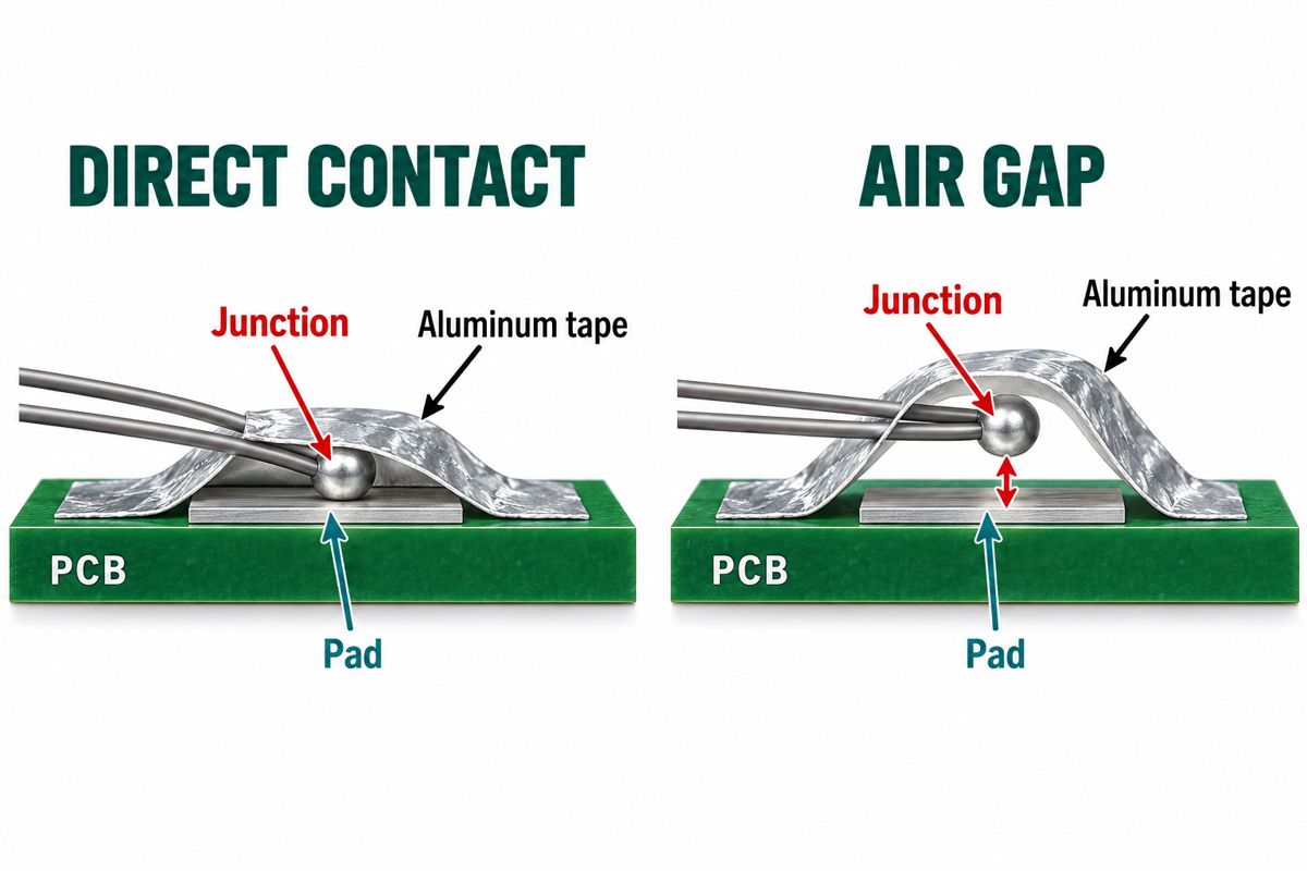
| Aluminum tape with suitable reinforcement | Enough clear board area to maintain bead contact | Lifting, trapped air or tension transmitted to components |
| Qualified adhesive | Limited space, with verified adhesion to the actual surface | Unverified cure, coverage or solder-mask compatibility |
| Polyimide tape alone | Do not assume it is an equivalent thermal attachment | Air pockets and a mechanically retained but poorly coupled junction |
The 2025 KIC/RIT comparative study shows why attachment must be evaluated on populated boards. Tape attached over components caused lifting during molten-solder exposure, and adhesive performance depended on the substrate. This is not evidence that every adhesive beats solder or that a method survives unlimited cycles. Select a candidate, document its installation and confirm repeatable contact on your assembly.
How do you attach a thermocouple for reflow profiling?
- Identify the board and point. Use an authorized profiling sample with the intended population, panel and support. Mark the channel and the exact measurement target. Do not drill or rework a customer assembly without an approved sample plan.
- Check the whole measurement chain. Match the thermocouple type to the logger input and connector. Confirm probe, insulation, attachment material and any in-oven logger protection are suitable for the intended exposure. An instrument’s display range is not the probe’s temperature rating.
- Prepare the chosen surface. For the soldered method, remove residual low-melting solder and contamination using a controlled rework process. For an adhesive, follow its own surface-preparation and curing instructions; “dry to touch” is not a substitute for that cure.
- Make the thermal contact. For solder attachment, position the junction first, heat the junction and target, then apply a small controlled amount of suitable solder. For conductive tape, keep the junction against the target and cover it without an air pocket. Reinforce tape edges where the qualified method requires it. For adhesive, maintain the intended junction position during the specified cure.
- Add separate strain relief. Route wires with slack and secure them away from the sensing junction. Do not let a cable pull on a component while its solder is molten. Check that exposed conductors do not touch each other before the intended junction.
- Inspect, record and run. Photograph the contact and restraint, check channel identity, then run the representative setup. After safe cooling, inspect for movement or damage before interpreting or repeating the measurement.
KIC’s solder-attachment application note supports the preparation, junction-first soldering and restraint principles. Its historical high-lead solder example is not a blanket material recommendation: follow the selected material’s safety instructions and your site’s handling controls, and segregate modified profiling samples from deliverable assemblies.
What are the Omega 5TC-TT-K-30-36 specifications?
The Omega 5TC catalog sheet provides a concrete ordering example. These are that product’s listed construction details, not a universal reflow-probe specification.
| Item | Listed value | Selection implication |
|---|---|---|
| Model | 5TC-TT-K-30-36 | Specify the complete code, not only “K-type” |
| Thermocouple type | K | Use a compatible measurement input |
| Wire size | 30 AWG; 0.25 mm nominal diameter | Wire diameter is not junction diameter or total insulated width |
| Insulation / termination | PFA / stripped leads | Connector and installation remain part of the system |
| Listed length / pack | 1 m / five probes | Check routing length and channel count |
| Separate TAP adhesive labels | 180°C maximum use temperature | Not suitable for exposure exceeding that limit |
This sheet does not establish the complete probe’s allowable reflow exposure, measurement tolerance or installed response time. Obtain those specifications before qualification. Do not transfer the TAP accessory rating to the probe, or infer a tape’s rating from its film name. Availability of calibration is not proof that a particular purchased probe has been calibrated.
Can a thermocouple on top of a BGA measure its solder joints?
It measures the package surface directly, not the buried joint. A KIC/RIT area-array study compared surface-mounted probes with a junction placed under a BGA. The relationship depended on package and board geometry. Do not apply a fixed temperature correction to every BGA.
If the acceptance requirement concerns a hidden joint, agree how that joint will be instrumented or how a surface proxy will be correlated. A sacrificial test assembly may be needed. Label an uncorrelated surface reading as a surface reading; a plausible-looking curve does not turn it into joint-temperature evidence.
Why does a reflow thermocouple read the wrong temperature?
Use the table as a troubleshooting sequence, not a diagnosis from curve shape alone. First confirm what the channel was intended to measure.
| Observation | Question to investigate | Next check |
|---|---|---|
| A sudden step followed by a different trace | Did the junction detach? | Inspect contact after cooling; repair and repeat before recipe changes |
| One channel disagrees with its previous run | Did the point, restraint, population or setup change? | Compare installation photographs and run records |
| Two readers disagree | Are probe type, connection and calibration evidence equivalent? | Check the measurement chain before declaring an oven fault |
| Good repeatability but unexpected soldering results | Is a surface or air reading being treated as a joint reading? | Recheck target identity and correlation; inspect other process causes |
Do not increase the peak simply to make an unexplained channel match another one. First determine whether the difference is real spatial variation or a measurement problem. Then compare valid traces with the actual paste and component requirements.
What should a reflow profile handoff include?
Keep one channel record per measurement point: channel ID; reference designator and pin/location; joint, body, board or air; probe part number; attachment material and method; photo; restraint location; run ID; post-run condition. Retain the raw trace alongside the oven settings, board revision, panel/support, paste and component thermal constraints. This is a practical handoff template, not a prescribed industry form.
When discussing PCB assembly, send that information with the BOM, placement data and assembly drawing. Contact PCBtry to review the build requirements and agree what profiling evidence is needed. Agree the sample, measurement locations and acceptance limits before treating a report as production approval.
Reflow thermocouple attachment FAQ
Can I suspend the probe just above the PCB?
Yes for a deliberately identified air measurement, but not as a substitute for direct joint contact. Record it as an air channel.
Is any K-type thermocouple suitable for reflow?
No. K-type identifies the thermoelectric pairing. The actual probe construction, insulation, attachment and exposure limits still need checking.
How do I avoid melting the probe insulation?
Confirm the exact probe’s rated exposure before the run. Keep connectors and equipment within their specified environments; do not rely only on the logger’s measurement range.
Is one probe enough to check the whole board?
One probe describes one location. Choose additional points from the assembly’s thermal risks and the evidence required; there is no universal channel count for every board.
Can I use a blank PCB instead of a populated board?
A blank board may support a limited exploratory check, but it does not reproduce the component population. Do not use it alone to qualify the populated assembly.
Can Kapton tape hold the thermocouple?
It can provide suitable restraint in a qualified installation. Holding the wire is different from coupling the junction; check material rating, contact and lifting.
Should I raise the oven temperature when solder does not reflow?
Not from an unverified reading. Confirm contact and measurement location first, then assess the valid profile against the paste and component limits.
Is a component’s operating-temperature limit its reflow limit?
No. Use the manufacturer’s soldering/reflow exposure specification for assembly, not the normal operating limit. Both apply to different conditions.



0 Comments