




FR4 is a flame-retardant, woven-glass-reinforced epoxy material used as the insulating base in many rigid printed circuit boards. It supports the copper circuitry and separates conductive layers. An FR4 PCB board is the finished circuit board built with that material—not simply a sheet of fiberglass or copper-clad stock.
For a straightforward design, your fabricator’s standard FR4 may be a sensible starting point. For a board with demanding assembly conditions, controlled impedance, or significant signal loss, “FR4” alone leaves important choices unresolved. The useful question is which material properties and construction details your design actually needs controlled.
FR4, Copper-Clad Laminate, and a Finished PCB
The terms often appear together on supplier websites, but they describe different things.
| Term | What it describes |
|---|---|
| FR4 material or FR4 substrate | The insulating glass-epoxy material supporting the circuitry |
| Copper-clad laminate | Cured insulating laminate bonded to copper foil, ready for circuit fabrication |
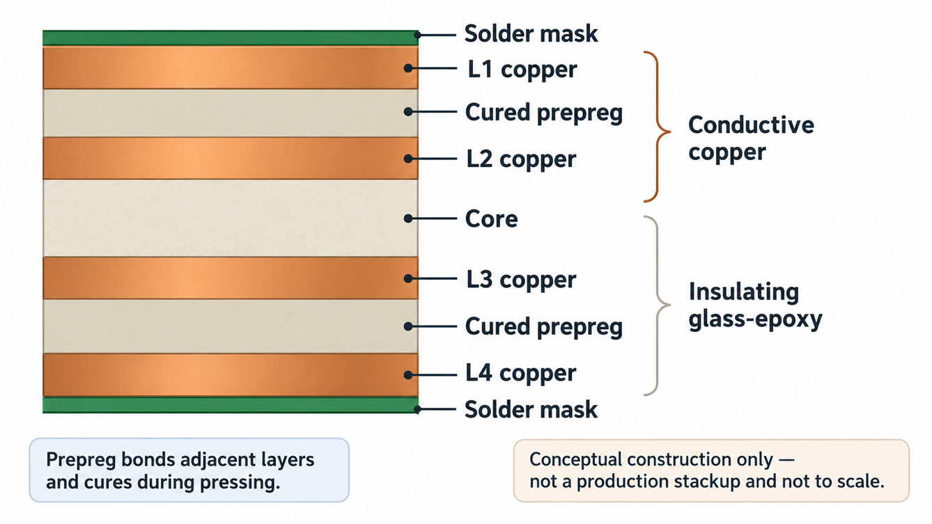
| Core | A cured laminate layer, commonly supplied with copper on one or both sides |
| Prepreg | Glass fabric impregnated with partially cured resin, used to bond layers during lamination |
| FR4 printed circuit board | The fabricated board, including its copper pattern, holes, and specified finishes |
In a multilayer construction, cores and prepreg help form the dielectric structure between copper layers. They are not interchangeable purchasing descriptions: the core is already cured, while prepreg flows and cures during the pressing process. Seeed’s FR4 construction overview illustrates how these parts fit into a stackup.
If you are buying an FR4 board for machining, confirm whether the order is for bare laminate, copper-clad stock, or a fabricated PCB. If you are ordering circuit boards, the material name does not replace the fabrication files and finished-board requirements.
FR4 also does not describe the solder mask color. The insulating substrate sits beneath the copper and surface coatings; a green board is not evidence of a particular laminate grade.
The Properties That Change a Material Decision
FR4 is a material category, not one product with a universal datasheet. A laminate manufacturer’s grade, glass construction, resin content, and test conditions affect the values you should use.
Rather than collecting every available property, start with the risk your board needs to address.
| Design concern | Properties or details to review | What to request |
|---|---|---|
| Heat during assembly | Tg, decomposition behavior, thickness-direction expansion, and relevant thermal test results | The proposed grade and its assembly-processing guidance |
| Impedance or timing | Dk, dielectric thickness, copper geometry, and the actual stackup | The fabricator’s proposed construction and calculation assumptions |
| Signal attenuation | Df, conductor loss, routing length, and the required bandwidth | A loss assessment using the proposed material and channel |
| Mechanical fit | Finished board thickness, tolerance, and construction | A finished-board specification, rather than laminate thickness alone |
| Material substitution | The properties your design depends on and the approved alternatives | A written substitution and approval rule |
These are separate questions. A material upgrade that helps one does not automatically resolve the others.
Tg Is Not the Board’s Maximum Operating Temperature
Glass transition temperature, or Tg, describes a change in the resin’s mechanical behavior. It is not a melting point, a continuous-use temperature rating, or proof that a board will survive a particular assembly process.
The measurement method matters, too. Isola’s FR408HR product information lists a Tg of 190°C by differential scanning calorimetry, or DSC, while its description identifies a 230°C Tg by dynamic mechanical analysis, or DMA. These are different measurements for the same material system—not two interchangeable specifications.
Before comparing grades, check that the Tg values use the same method. Then review the other thermal properties and the intended processing conditions. Choosing a larger number without that context can create a misleading comparison.
Dk and Df Answer Different Electrical Questions
Dielectric constant, or Dk, is relevant to signal propagation and impedance. Dissipation factor, or Df, describes dielectric loss. Neither can be reduced to one dependable number for every FR4 circuit board.
For impedance work, the material data must connect to the actual dielectric layers and trace geometry. An internet calculator populated with a generic FR4 value is a preliminary estimate, not a confirmed production stackup. Our FR4 dielectric constant guide covers that distinction in more detail.
For loss-sensitive channels, look beyond Dk. Altera’s stackup guidance explains the role of dielectric absorption in transmission-line loss. Texas Instruments also treats material choice as part of the channel design in its PCIe Gen 5 layout application note.
Does Higher Tg Mean Better FR4?
Higher Tg addresses a thermal property. It does not, by itself, establish lower electrical loss, a suitable impedance stackup, or adequate reliability for your application.
For example, Isola classifies 370HR as a thermally robust material with a typical DSC Tg of 180°C. It positions FR408HR as a mid-loss material. Those product descriptions illustrate why you need to compare thermal and electrical requirements separately; they do not establish which product your fabricator stocks or which is right for your board.
A useful review starts with the problem:
- If assembly exposure is the concern, review the thermal behavior and processing guidance for the proposed material and construction.
- If the channel loses too much signal, assess the relevant electrical properties and complete routing path.
- If the board must fit a connector or enclosure, confirm finished thickness and tolerances.
An increase in Tg is not a substitute for any of those checks. Equally, a low-loss laminate does not remove the need to validate the thermal and manufacturing requirements.
How to Choose an FR4 PCB Material
Start With the Conditions the Board Must Meet
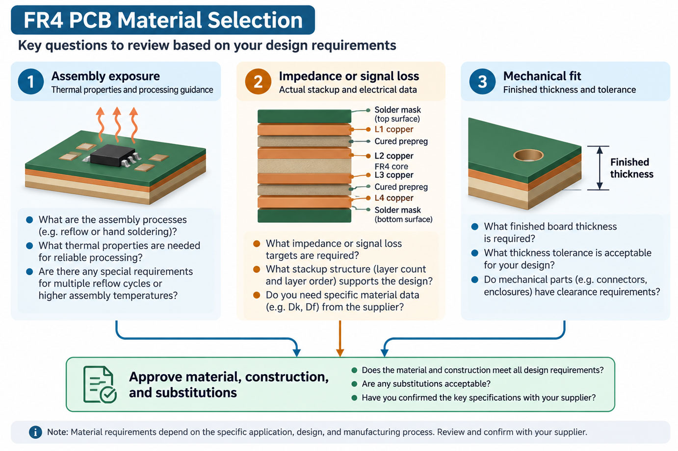
Write down the assembly process, expected service environment, mechanical constraints, and any electrical requirements that depend on the dielectric. You do not need a full material study for every simple board. You do need to identify the conditions that could make an unspecified substitute unacceptable.
For a basic prototype without sensitive electrical or thermal requirements, ask the fabricator what its standard FR4 option includes. For a controlled-impedance board, obtain the proposed stackup before treating trace widths as final. For a loss-sensitive channel, evaluate the material in the channel model rather than selecting it from a general-purpose comparison chart.
Ask for the Actual Grade and Construction
Request the manufacturer and grade, the relevant datasheet, and the stackup when construction affects performance. “High Tg” and “standard FR4” are useful conversation starters, but they do not identify every parameter or approval condition.
There is also no universal frequency at which all FR4 becomes unusable. Material properties, trace length, geometry, and the allowed loss all influence the decision. A short connection and a long channel can have different requirements even when the nominal signal frequency is similar.
Decide What Can Be Substituted
An exact material designation can be appropriate when the design or qualification depends on it. Where alternatives are acceptable, define the requirements they must satisfy and who approves a change.
For example, a hypothetical specification approach might allow a fabricator to propose an alternative laminate, provided it supplies the relevant material data and revised stackup for approval before production. The design team would then review any effect on impedance, processing, and qualification.
That is a method for controlling a substitution, not a complete fabrication note. The actual limits must come from the design and its validation requirements. Simply writing “FR4 or equivalent” leaves the meaning of equivalent open to interpretation.
What to Confirm Before Ordering
For an FR4 PCB quotation, separate the material request from the rest of the board package:
- Material: State the required grade, or ask the fabricator to identify its proposal and any permitted alternatives.
- Construction: Provide the layer count, finished thickness and tolerance, copper requirements, and stackup constraints that matter to the design.
- Electrical requirements: Identify controlled-impedance nets or loss-sensitive channels and the applicable acceptance requirements.
- Processing and environment: Describe relevant assembly exposure and service conditions so the material review has a defined purpose.
- Approval: Identify who must accept a material or stackup change before fabrication.
For a purchase of laminate stock rather than a completed board, specify that distinction explicitly, along with the sheet dimensions, material thickness, and whether copper cladding is required.
The result should be a clear agreement about what will be built. “FR4” identifies the starting material category; the approved grade, construction, and board requirements make it usable as a production specification.
Frequently Asked Questions About FR4 PCB Material
Is writing “FR4” on the fabrication drawing enough?
It can be a starting point when the fabricator’s standard material is acceptable, but confirm what that option includes. Add the requirements that affect your design, such as the permitted grade or substitution rule, finished thickness and tolerance, and any controlled-impedance or assembly constraints. Unresolved requirements should be identified before the build is approved.
Can the FR4 grade change between a prototype and production?
Only after the change has been reviewed against the requirements the prototype was intended to validate. A different grade or construction may require new electrical, thermal, manufacturing, or qualification checks. Record the approved material and stackup for each release rather than assuming that two boards described as FR4 are interchangeable.
Does a material datasheet confirm the performance of the finished PCB?
No. A datasheet describes the material under stated test conditions. The finished board also depends on its construction, copper geometry, manufacturing process, and application. Use the material data as an input to the design and agree on any required finished-board verification separately.
What if the required FR4 grade is unavailable?
Ask the fabricator to identify a proposed alternative and provide its relevant data and construction details. Compare it with the requirements that made the original grade necessary, then document who approves the change and whether validation must be repeated. Similar Tg values or the label “FR4 equivalent” alone do not establish interchangeability.
Prepare Your FR4 Material and Stackup Requirements for a Quote
Before requesting an FR4 PCB quote, gather the fabrication files, layer count, finished thickness and tolerance, copper requirements, and build quantity. Identify any specified material grade, controlled-impedance targets, assembly exposure, or application constraints, and state whether substitutions need approval.
For a Thindry project inquiry, send your FR4 PCB requirements through the contact page or email sales@pcbtry.com. If the material grade is not yet decided, describe the design requirements and ask which material and stackup assumptions the quotation will use.



0 Comments