




What does a PCB design review actually approve?
A PCB design review process is a structured check that a specific board revision is ready for its next stage. Reviewers compare the circuit, layout and manufacturing files with the product requirements, record problems, verify corrections and decide whether to release that revision. The result should be a traceable decision, not simply a meeting or a clean design-rule report.
Think of a board with a connector that has the right footprint but faces the enclosure wall. The layout software may find no copper-spacing violation. The factory may be able to make it accurately. Yet the cable cannot be inserted. That is why design review must connect electrical intent, physical fit and manufacturing information.
Three checks answer different questions. DRC, or design rule checking, compares the layout with configured rules. DFM, or design for manufacturing review, examines whether the proposed construction can be made with the selected process. Design review asks whether the implementation meets the actual product requirements. Passing one does not automatically pass the others.
The method below is a suggested working template, not a certification procedure or an exhaustive safety checklist. Adapt it to the product, interfaces and applicable standards. A successful review reduces avoidable errors; it cannot replace prototype testing or qualification. When using an external PCB design service, agree who reviews the design and who authorizes release before work starts.
Run the review from frozen inputs to a release decision
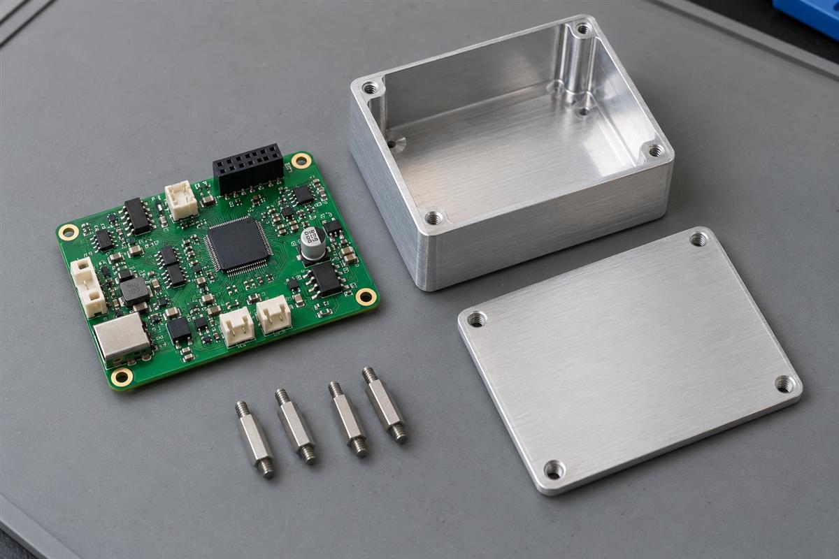
Use one identified revision throughout the review. Establish the inputs first, collect findings against that revision, and approve the corrected release only after the relevant checks have been repeated.
1. Define what is being approved
Write a short review scope: board identifier, revision, intended build, operating conditions and next decision. For example: “Revision B, ten engineering prototypes, low-voltage bench evaluation, not approved for customer shipment.” Include measurable requirements such as connector assignments, supply range, board envelope and required interfaces. “Works reliably” is not a checkable requirement.
2. Freeze the input package
Provide the schematic, PCB layout, bill of materials, component data sheets, mechanical model or dimensioned drawing, proposed stackup and current rule reports. Identify files with a shared revision or a manifest that maps their individual revisions. Include changed items since the last review. A reviewer looking at yesterday’s schematic and today’s layout is reviewing a combination that may never be manufactured.
3. Assign reviewers and evidence
The author explains intent; another qualified person should challenge important assumptions where practical. Small teams may combine roles, but the responsibilities still need names. An outside fabricator can assess manufacturing questions without becoming responsible for the product’s electrical design.
| Review area | Suggested owner | Evidence to bring |
|---|---|---|
| Circuit function | Electrical designer and peer | Requirements, calculations, data-sheet references and interface mapping |
| Layout and physical fit | Layout and mechanical reviewers | Layer views, connector orientation, dimensions and enclosure clearances |
| Fabrication and assembly | Manufacturing contact | Stackup agreement, fabrication notes and assembly constraints |
| Verification and release | Test owner and release authority | Test access plan, closed findings and exact release manifest |
4. Inspect by risk, not by screen position
Start with faults that could damage hardware, prevent bring-up or force a respin. Follow each important interface from connector to circuitry and back through its return path. Then review physical access and manufacturing constraints. Do not spend the whole meeting polishing silkscreen while supply ratings or connector pin assignments remain uncertain.
5. Resolve findings and repeat affected checks
Record the location, risk, required action, owner and verification evidence for every finding. After an edit, rerun the checks it may affect. Moving a connector changes more than its coordinates: cable access, mounting clearance, routing and assembly drawings may all need another look.
6. Make an explicit release decision
Choose release, hold, or a tightly defined limited-build decision. A limited build should state the known deviation, permitted quantity or use, responsible approver and verification plan. Do not use it to bypass unresolved safety or mandatory compliance requirements. Sign off the actual output package rather than a file name that someone might overwrite later.
Check electrical, physical and manufacturing risks together
A useful checklist pairs each question with evidence and a reason to stop. The following is a starting point; add device-specific guidance and the actual manufacturer’s limits rather than assuming one set of dimensions fits every board.
| What to check | How to check it | Hold the release when |
|---|---|---|
| Power and component ratings | Compare expected operating and transient conditions with the selected part’s requirements and ratings; retain calculations | A rating, sequence or protection assumption remains unverified |
| Connector mapping and polarity | Trace named signals through schematic pins, footprint pads and the mating connector drawing | Viewing direction, pin numbering or cable mapping is ambiguous |
| Footprints and assembly orientation | Compare land pattern, package variant and pin-one orientation with the exact ordered component | The BOM package and installed footprint do not agree |
| Signal and return paths | Inspect relevant layers together; check reference-plane interruptions and interface-specific routing requirements | A critical path depends on an unexplained discontinuity or missing constraint |
| Mechanical envelope | Check board outline, holes, fasteners, component height and mating access against drawings or a fit model | The board fits alone but the cable, tool or enclosure does not |
| Manufacturing construction | Compare stackup, holes, copper features, finish and tolerances with the agreed fabrication specification | Different documents describe incompatible constructions |
| Bring-up and test access | Walk through programming, power-up and measurement access using the proposed fixture or bench method | A required connection cannot be reached after assembly |
| Output consistency | Open exported fabrication data separately and compare it with the approved source revision | Layers, drills, outline or variant information disagree |
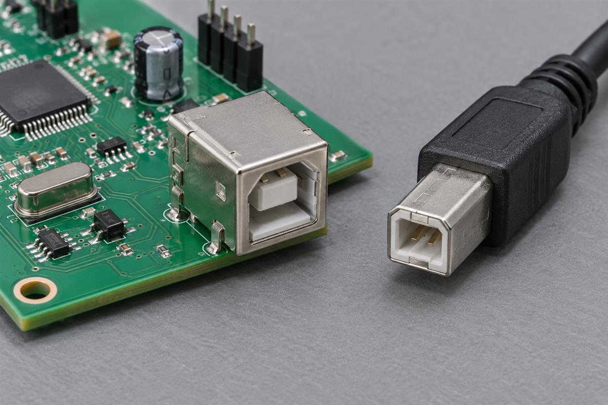
For a connector review, avoid the vague note “check polarity.” Write “verify J3 pin 1 against the mating-plug drawing viewed from the specified face.” That sentence identifies a location, reference and action. Likewise, “check impedance” needs a target, tolerance, proposed stackup and responsible confirmation, not a universal trace width copied from another board.
Public checklists are prompts, not substitutes for engineering judgment. Altium’s PCB design review checklist covers several review domains and explains that a board-specific list may need additions. TI also publishes device-specific schematic checklists; use the guidance for the component actually in your design, not an unrelated example.
Close findings with evidence, not a green status
A finding is closed when someone verifies that its acceptance condition is met on the intended revision. “Changed,” “discussed” and “task completed” do not provide that evidence by themselves.
Consider this hypothetical finding: the enclosure drawing allows 8 mm between the PCB surface and the lid, but a connector body is 9 mm high. The nominal interference is 9 – 8 = 1 mm, before tolerances or cable needs are considered. Making the board outline smaller will not fix this height conflict. The team must change the component, location or enclosure and then verify the resulting geometry with the relevant tolerances.
| Field | Example entry |
|---|---|
| Finding and location | DR-07: J3 exceeds lid envelope on revision B |
| Required action | Select a compatible lower-profile connector or revise the mechanical design |
| Owner | Named electrical owner with mechanical reviewer |
| Acceptance evidence | Updated part drawing, footprint check and reviewed clearance assessment |
| Closure record | Reviewer, date, corrected revision and link to supporting files |
After changing that connector, check the mating plug and pin mapping again. A replacement that solves height may introduce a different orientation or land pattern. This is why closure includes affected checks, not merely the original symptom.
Altium 365’s design review documentation describes version-specific review snapshots and approval decisions. Regardless of software, retain the revision, evidence and decision together. A tool’s status label is useful administration; it is not a measurement or a functional test result.
Build a fabrication release package that cannot be mixed up
The release package should identify exactly what the supplier is authorized to build. Export it from the reviewed revision, inspect the exported files, and keep the approved set separate from working edits.
- Identity: board number, revision, variant, date and a file manifest.
- Fabrication data: the supplier’s accepted data format, drill information, outline and necessary drawings.
- Construction: agreed layer stack, material requirements, board thickness, copper requirements, finish and controlled characteristics.
- Assembly, when ordered: BOM, placement data, assembly drawing, polarity notes and do-not-populate positions for the selected variant.
- Verification scope: required inspections, electrical testing and any separate programming or functional-test instructions.
- Release decision: approver, closed findings, permitted deviations and the procedure for handling supplier questions.
Use file checksums if your release system supports them. A checksum can show that a file has changed; it cannot prove that the original file was correct. If a supplier requests a change after release, review its impact, approve it explicitly and issue a traceable replacement package. Do not let an informal email silently become a second design revision.
For an assembled build, align the package with the scope of PCB assembly. A bare-board electrical test and a powered functional test of an assembled product are different deliverables. Name the required test and its acceptance criteria instead of writing only “fully tested.”
Before requesting a build, send PCBtry the reviewed files and open manufacturing questions, together with quantity, stackup requirements and assembly or test scope. Ask which construction assumptions need confirmation before ordering. Your team remains responsible for product requirements and design approval; manufacturing feedback helps close the fabrication and assembly questions.
PCB design review questions
When should a design review happen?
Review important architecture and component decisions before routing locks them in, then review the completed implementation before release. Revisit affected areas after material changes. Waiting until all files are exported makes avoidable changes more expensive.
Is a clean DRC report enough?
No. It only addresses the rules configured and checked. It does not prove that a connector mates, that the circuit meets its requirements or that the selected rule values are appropriate.
Who should approve the review?
Assign a release authority within your team and obtain input from the relevant electrical, mechanical, manufacturing and test owners. A supplier’s DFM response is not a blanket approval of product function.
Can a single-person team review its own board?
Yes, using explicit evidence and a separate review pass, but it lacks independent challenge. Seek targeted peer review for unfamiliar or high-consequence areas. Do not treat self-review as independent verification.
Do prototypes need the same checks as production?
The scope can differ, but identify the build purpose and permitted limitations. Even a prototype needs correct power connections, usable interfaces and manufacturable outputs. Prototype approval does not automatically authorize production shipment.
What should happen to a not-applicable checklist item?
Record why it does not apply. For example, an assembly programming step may be irrelevant to a bare-board order. An unexplained blank cannot distinguish an intentional exclusion from a missed check.
Must every edit trigger a full review?
Assess the change and repeat all affected checks. A minor text correction may need a narrow review; a changed power component, connector or stackup can affect several disciplines and require broader reassessment.
How do we know the review is finished?
The scope has been covered, blocking findings are resolved, accepted deviations are documented, and the approver has identified the exact release package. “The meeting ended” is not an exit criterion. Keep that package and its approval available for the next revision.



0 Comments