




What Does Double-Sided PCB Assembly Mean?
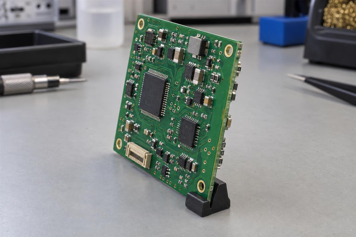
The double-sided PCB assembly process mounts components on both faces of a circuit board. A common surface-mount route is to print solder paste, place parts and reflow the first face, then turn the board over and repeat for the second. The second pass must be planned around the components already underneath the board.
This is not the same as manufacturing a two-layer bare PCB. Copper layer count describes the wiring inside and on the board; assembly sides describe where components are fitted. A multilayer board can have components on both faces, while a two-layer board can have components only on one face.
Imagine a controller with small resistors on one face and a large power module on the other. Fitting everything successfully is only part of the job. The assembler must also decide which face goes first, how to support the populated board after flipping it, and what evidence will release the completed assembly. This guide covers that two-pass SMT route. Through-hole parts and heat-sensitive items may need additional operations.
The Double-Sided PCB Assembly Process, Step by Step
Keep the two faces in one controlled manufacturing route. Calling them first-pass and second-pass faces avoids the mistake of assuming that a drawing’s “top” face must always be assembled first. The broader PCB assembly process also includes material preparation and final release.
Step 1: Match the files and agree on the assembly order
Start with the released BOM, placement data for both faces, assembly drawings and board revision. Check that every fitted reference designator has a matching part and location. Confirm how the assembler interprets bottom-side rotation and mirroring; do not manually mirror a placement file merely because the board will be flipped.
Flag tall, heavy or temperature-restricted parts before programming the line. Ask for a first-article drawing or placement review showing the proposed side order and any parts installed later. This catches wrong-side placement and process conflicts before materials are consumed. An unresolved file mismatch is a hold point, not something to correct by guessing at the machine.
Step 2: Print and place the first face
The inputs are the bare board or panel, approved stencil, paste and verified component program. The aim is controlled paste deposits and correctly oriented parts. Paste misalignment can become a solder bridge; a wrong rotation can become a correctly soldered but electrically incorrect assembly.
Review paste deposits and first placements against the agreed inspection plan before reflow. Fiducials are optical registration marks used to align the board with equipment; Eurocircuits explains their role in printing and placement. Agree on usable marks for both faces and the panel rather than relying on silkscreen edges as alignment references. Retain the first-article disposition or inspection record.
Step 3: Reflow and inspect the first face
Reflow melts the solder paste so it forms joints between terminations and pads. Use the qualified process for this board, paste and component combination. Inspect the first face after cooling so second-side work does not conceal an existing issue.
Record defects by reference designator and resolve significant placement or soldering problems before continuing. For example, a missing first-side capacitor is easier to trace now than after the finished board fails a functional test. The release evidence should identify the board revision, process recipe and inspection disposition, not just state “first side done.”
Step 4: Flip, support and assemble the second face
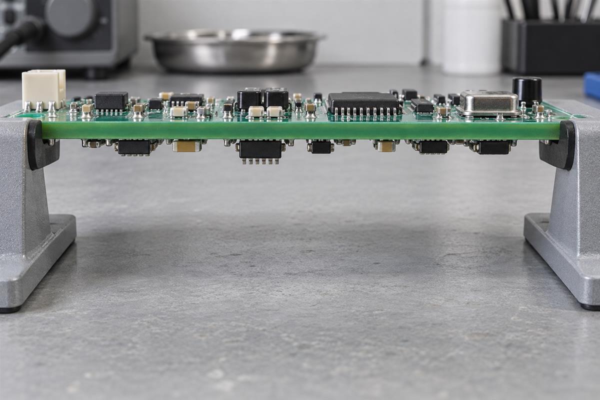
The input is now a partly assembled board, not a flat bare panel. Check the support arrangement with the first-side components facing down before printing paste on the exposed face. A support pin or carrier must not press on a component body or solder joint unless the tooling was specifically engineered for that contact.
Verify clearance around bottom-side components, tooling and handling edges. Then print and place the second face using its own approved program. A dry setup check or tooling drawing is useful evidence: it can reveal interference before a crushed component or unstable print causes scrap. Component courtyards also need access for manufacturing and repair; clearance guidance should be agreed with the selected assembler, not copied as a universal spacing rule.
Step 5: Run the qualified second reflow
The first-side joints may become molten again while their components face downward. A successful first pass therefore does not qualify the second automatically. Use a validated second-pass setup, then check that first-side components remain correctly attached and that the newly assembled face meets its inspection requirements.
If a part moves or drops, isolate affected units and investigate the side sequence, retention and actual process conditions. Do not treat a replacement component as proof that the production cause has been removed. Save the trial disposition and any approved route change before releasing the next lot.
Step 6: Complete remaining operations and release the board
Install any parts deliberately excluded from the two SMT passes using their approved process. Inspect both faces and perform the specified electrical or functional tests. The output is a traceable assembly with an accepted revision and test result, not simply a board that survived two oven passes.
Define acceptance criteria and responsibility for deviations before production. The PCBA quality-control guide helps separate inspection coverage from electrical verification. A visual pass does not establish that firmware, power rails or every signal path works.
Which Components Can Stay Underneath During Second Reflow?
There is no reliable universal rule based only on component size. TI’s power-module soldering guidance explains that upside-down retention depends on component mass, solder-pad geometry and alloy surface tension. It also notes that heavy parts are normally reflowed last. Apply the relevant package guidance and validate the actual assembly.
Molten solder is not simply a liquid puddle that releases every part: its surface forces can retain suitable components. But that mechanism is not a guarantee for an unfamiliar package. Use the following table to start a review, not to approve a design without testing.
| Situation | Question to resolve | Useful release evidence |
|---|---|---|
| Small first-side passives | Does the selected process retain correct position and acceptable joints? | Representative second-pass trial and inspection results |
| Heavy module proposed on the first face | Can it move to the second face or be fitted later? | Package guidance and approved sequence or retention solution |
| Significant parts on both faces | Is a qualified carrier or other engineered retention method needed? | Tooling review, thermal verification and trial disposition |
| Limited-temperature component | Is it compatible with the planned route at all? | Part-specific process limits and an approved installation method |
Adhesive is not a default cure. If it is proposed, ask how its location, cure, compatibility and later repair will be controlled. Likewise, switching to a lower-temperature solder system is a process change requiring qualification, not a shortcut that can be chosen from melting point alone.
How Do You Track Two Reflows and Later Rework?
Track what each component actually experiences, not just how many times the board enters the oven. TI specifies that allowable reflow temperature and cycle count are device-dependent. Its limits must come from the applicable part documentation, including moisture-handling requirements.
Intel’s SMT assembly guide calls for both assembly stages to meet their profile targets and notes that different thermal mass can require different settings. An oven recipe is a set of machine commands; a measured profile records the temperatures reached on the assembly. They are not interchangeable evidence.
For a hypothetical board, label a first-face IC U1 and a second-face IC U2. The simple planning record below makes a common oversight visible. It is not a declaration that any specific IC can tolerate the route.
| Item | First reflow | Second reflow | Review before later repair |
|---|---|---|---|
| U1 fitted on first face | Present | Present again | Two planned oven exposures already recorded |
| U2 fitted on second face | Not installed | Present | One planned oven exposure recorded |
| Board and first-face joints | Processed | Processed again | Review the location and extent of additional heating |
A local repair can also heat nearby parts, so “only U2 was replaced” does not automatically mean that U1 experienced no extra heating. Record the repair method and assess the affected region. Stop when documentation cannot establish compatibility; do not invent a permitted cycle count.
Request representative profile records for both build states, measurement locations and the relevant material/component limits. Do not copy a peak temperature or conveyor speed from another board. Board support and warpage also deserve review; a material’s Tg value alone is not an assembly-process qualification.
What Should You Inspect and Put in the RFQ?
Specify the evidence needed to accept the assembly before comparing prices. “Double-sided SMT included” does not explain whether the quotation covers tooling, second-pass qualification, hidden-joint inspection or functional testing.
| Observed problem | First checks | Do not assume |
|---|---|---|
| First-face part missing after second pass | Confirm it was present beforehand; review retention and handling records | Every missing part fell off in the oven |
| Damaged underside component | Review support/tooling contact and handling clearance | The temperature profile caused all physical damage |
| Repeated bridges at one location | Compare paste deposit, alignment, footprint and placement evidence | A hotter reflow profile will fix the root cause |
| Board looks correct but fails electrically | Use the circuit’s approved test plan; investigate relevant nets and parts | Optical inspection covers hidden joints or circuit function |
Hidden connections may require additional inspection selected for the package and failure risk. Agree on what the chosen method can and cannot detect, and how suspect results will be resolved. Do not substitute a generic “100% inspection” statement for a defined test scope.
Copy this checklist into the RFQ:
- Board revision, manufacturing data and panel drawing, if applicable.
- BOM with manufacturer part numbers and approved substitution rules.
- Placement files for both faces, with coordinate origin, units and rotation convention confirmed.
- Assembly drawings showing polarity, do-not-fit positions and proposed late-installed parts.
- Restrictions for heavy, tall, moisture-sensitive or temperature-limited parts.
- Required inspection, test coverage, acceptance criteria and traceability records.
- Prototype and production quantities, including whether tooling and profile validation are quoted separately.
Send this package through PCBtry’s contact page and request confirmation of the proposed assembly sequence, tooling needs and inspection scope. Resolve unclear items before authorizing production. That gives both buyer and assembler a concrete basis for a quotation and a release decision.
Frequently Asked Questions
Is double-sided assembly the same as a two-layer PCB?
No. Assembly refers to components on two faces. Layer count refers to copper wiring layers. Specify both when requesting a quote.
Must the top face be soldered first?
No. Top and bottom are design labels. Manufacturing order should be agreed from the parts, handling and qualified process.
Will all first-side parts fall off during the second reflow?
No. Suitable joints can retain parts, but unfamiliar or heavy packages require a retention review and validation rather than an assumption.
Does every double-sided board need glue?
No. Do not add adhesive without a process reason. Ask what it solves and how it affects curing, inspection and repair.
Can the same oven settings be used for both faces?
Possibly, if the measured results meet all applicable limits in both build states. Identical settings are not proof of equivalent temperatures.
Can through-hole parts be included?
Yes, but their installation and soldering route must be planned separately where needed. Check lead access and possible effects on nearby SMT parts.
Does double-sided assembly cost exactly twice as much?
No. A second process pass adds work, but total cost also depends on part count, programming, tooling, inspection and testing. Compare itemized scopes.
What is the most useful question before releasing a first article?
Ask which records demonstrate that both faces, the second-pass risks and the agreed electrical tests passed. A finished-board photograph alone cannot establish that.



0 Comments