
Introduction
A Printed Circuit Board can be likened to a city that never sleeps, as its components work together in a manner analogous to a city’s operations, forming a complete system to power our devices. Once you start thinking along these lines, the concept of having so many different components on a PCB becomes much less foreign. So, what are the Components on a PCB?To help you get started, we will introduce the common electronic components mounted on a Printed Circuit Board!
What are PCB Components?
Printed Circuit Board components are the electrical parts used to fabricate the entire circuit board. A PCB is composed of electrical components such as diodes, capacitors, fuses, and resistors. For a PCB to function effectively, each component must play its role. If one part fails, the PCB may not perform as intended.
What are the Common Electronic Components on a PCB?
Each electrical component making up a PCB is crucial for the operation of the device it will be connected to. Various PCB components, such as transistors, fuses, resistors, and capacitors, all contribute to the smooth operation of a device. If one of these components fails, the PCB as a whole may cease to function, which will impact the product’s performance.
PCBs can be single-sided (having only one copper layer) or multi-layered (with up to 20 or more layers). As the number of layers increases, the PCB becomes more complex, and so does the matching device it powers. Furthermore, more layers equate to more electronic parts.
A robust PCB can undoubtedly support over a dozen electronic components. But for beginners, we recommend starting with the most typical parts.
| Component | Image | Description |
|---|---|---|
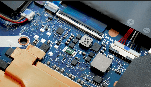
| Resistors | 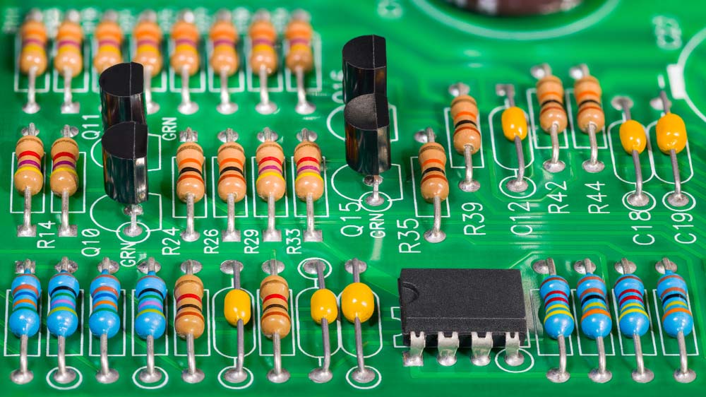 | A resistor opposes electrical current in a circuit, useful for adjusting signal levels, splitting voltage, or controlling LED brightness. Types include fixed and variable resistors, with the latter ideal for real-time adjustments or sensing conditions like light and humidity. |
| Capacitors | 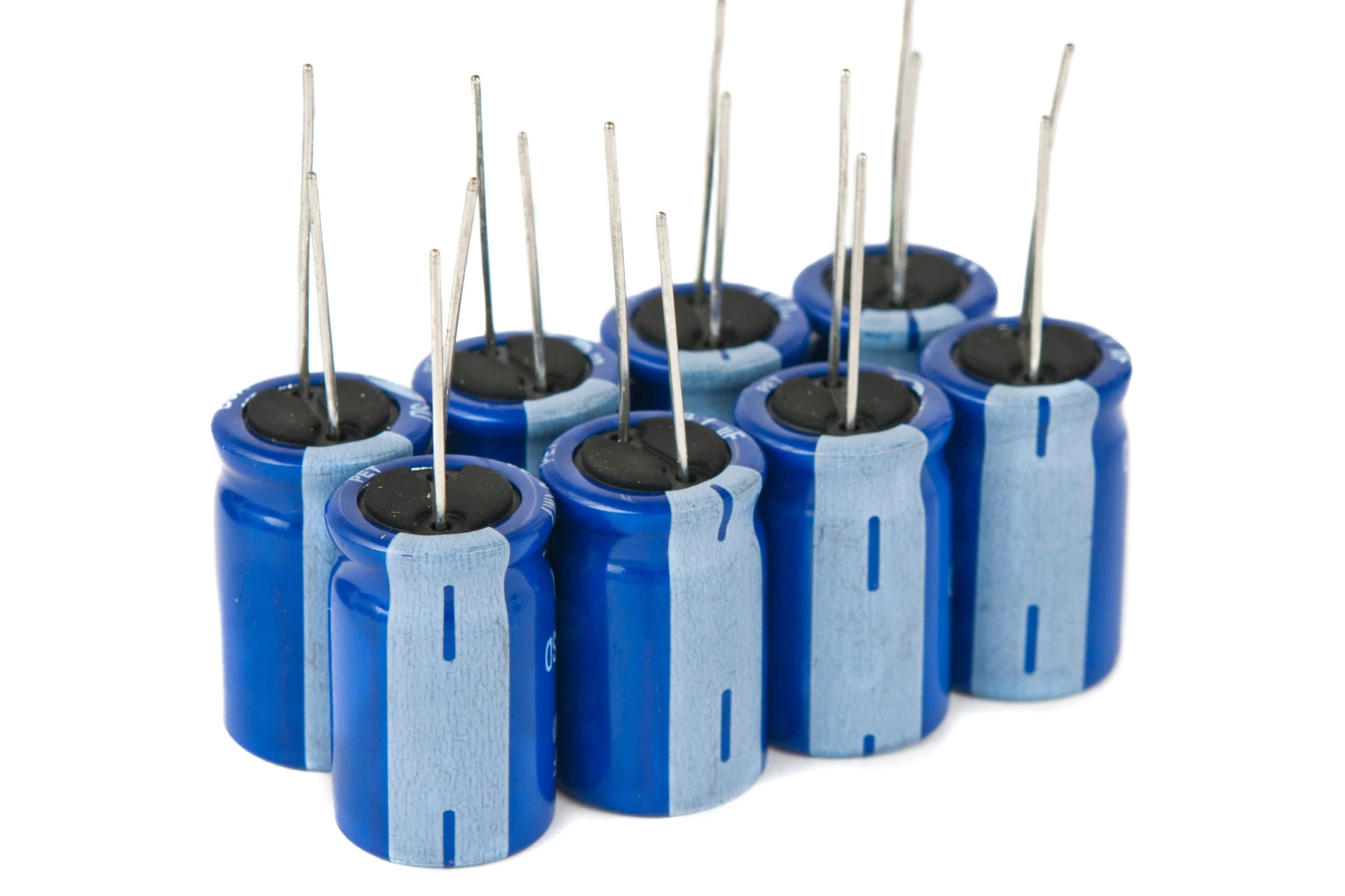 | Capacitors store electrical charge on two plates separated by a dielectric, air, or vacuum. They filter noise, stabilize voltage, and create circuit resonance. |
| Diodes | 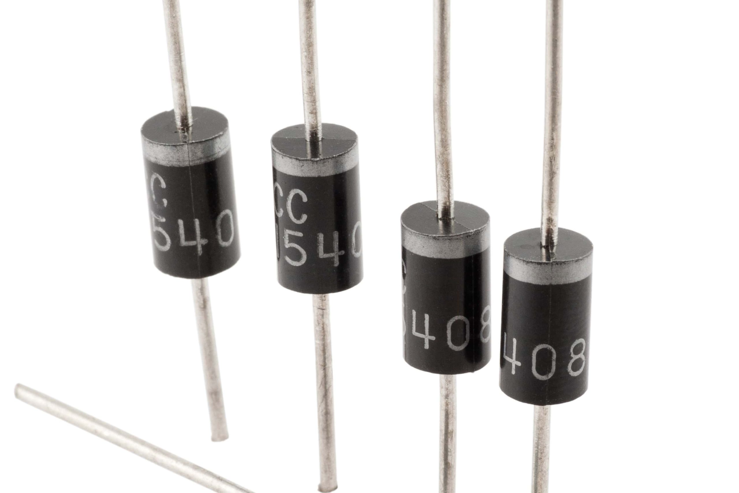 | Allow current to flow in one direction while blocking it in the opposite. |
| Inductors | 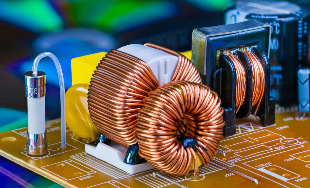 | An inductor stores energy as a magnetic field when current flows through it. Made of insulated wire around a core, it resists changes in current due to Lenz’s law. |
| Transformers | 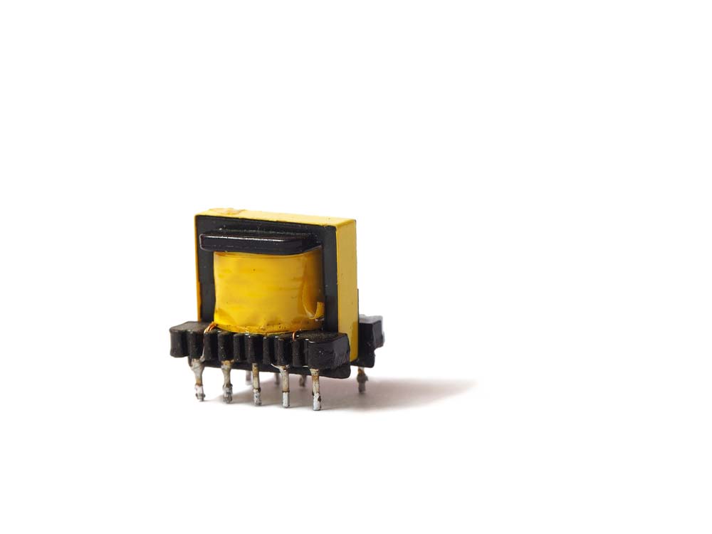 | A transformer transfers AC energy between circuits through magnetic coupling, stepping up or down voltage, making it ideal for audio amplifiers and power supplies. |
| Crystal Oscillators |  | Generate precise clock signals for timing in circuits. |
| Sensors | 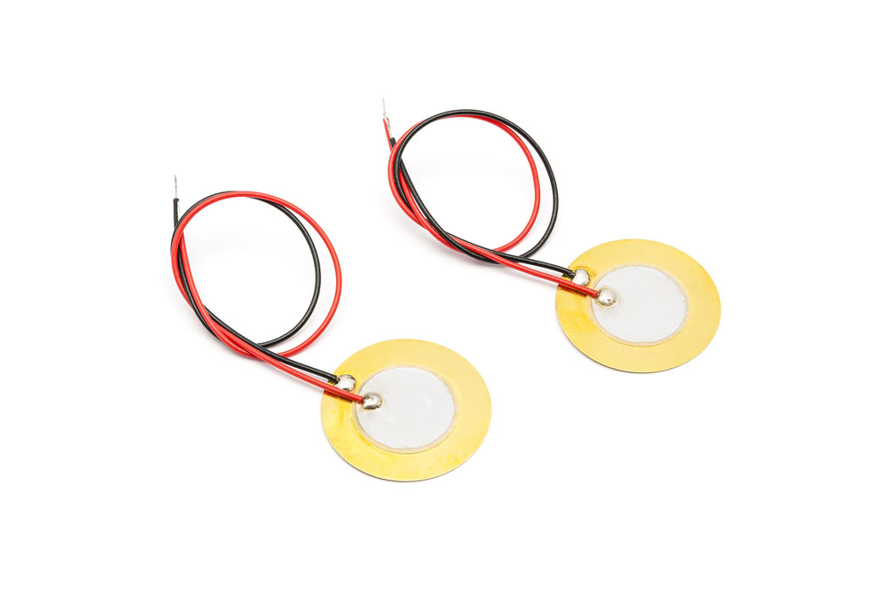 | Detect physical conditions (e.g., temperature, pressure) and convert them to signals. If you’re working on security or automation systems, Passive Infrared (PIR) sensors are essential for detecting motion in a room or space. |
| Silicon Controlled Rectifier | 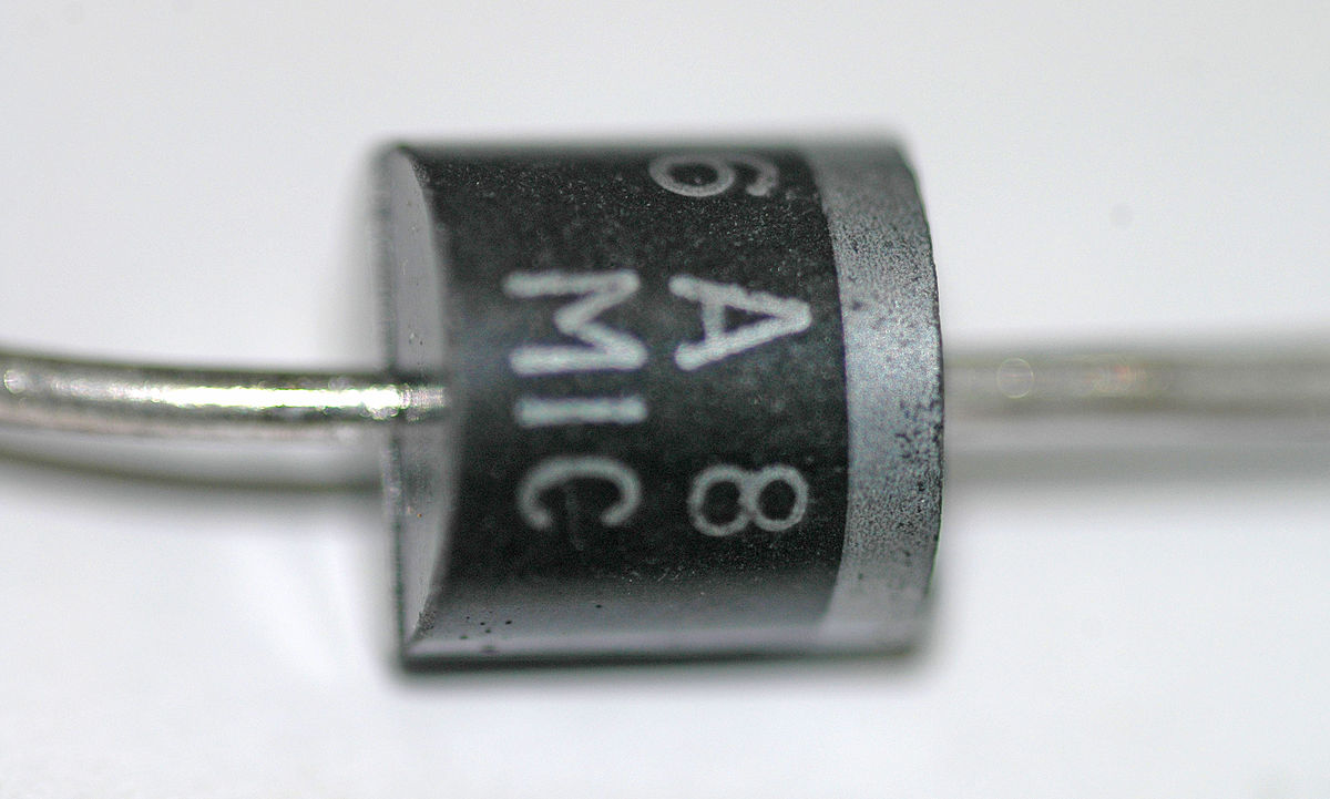 | A semiconductor switch that controls large amounts of power with small signal inputs. |
| Battery | 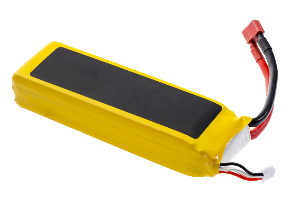 | Store energy to power the circuit. |
| Relays | 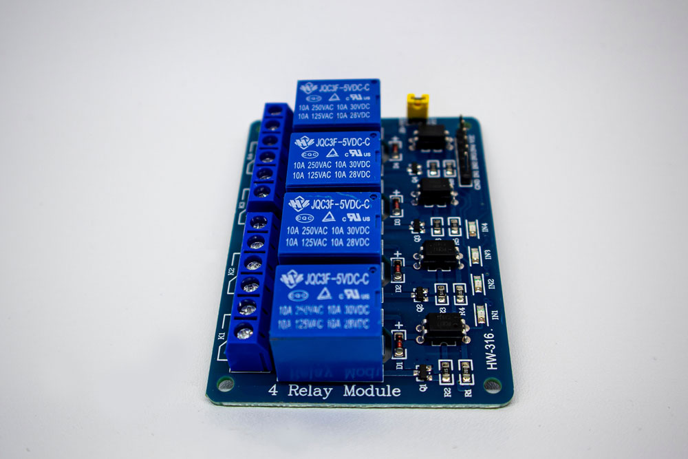 | Electrically controlled switches used to control circuits. |
| Blank PCB | 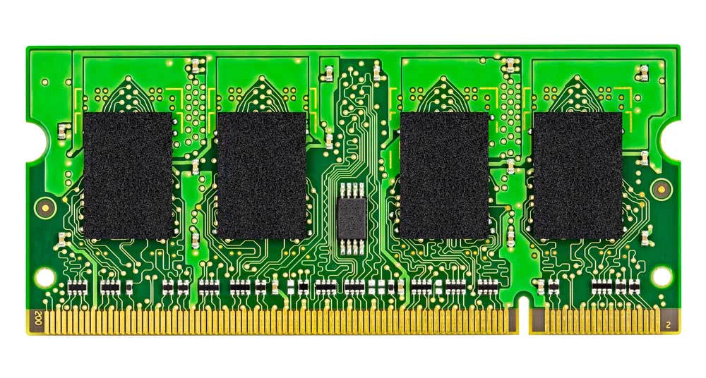 | The foundation of a circuit, where components are placed and connected. |
| LED | 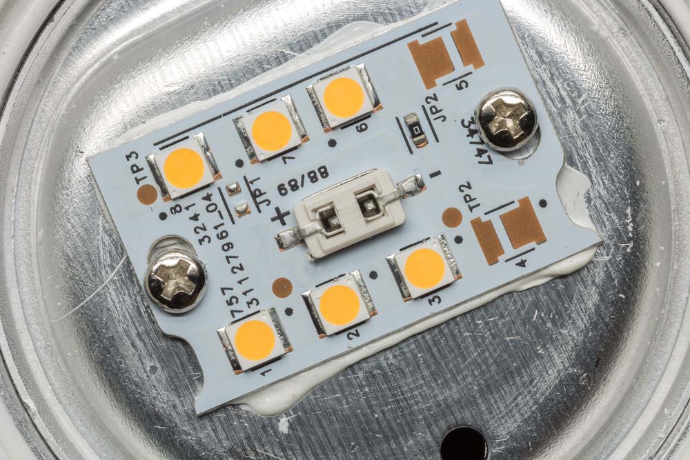 | Light-emitting diode used for indication or lighting. |
| Screen Printing | 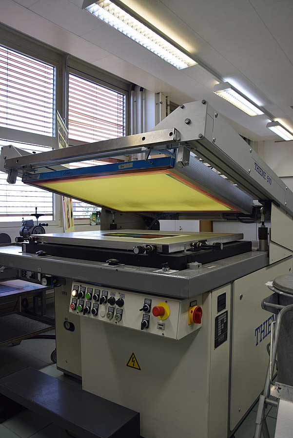 | Method for applying ink to the PCB surface to label components. |
| Fuse | 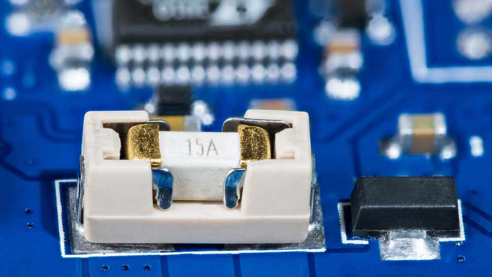 | Fuses contain a wire rated for specific voltage and current. If exceeded, the wire melts, protecting the circuit from overcurrent damage. For more on protecting your circuits, consider understanding fast-blow fuses, which offer rapid protection in high-current scenarios. |
| Digital Electronics | Electronics that use digital signals for processing. | |
| Field-Effect Transistor | 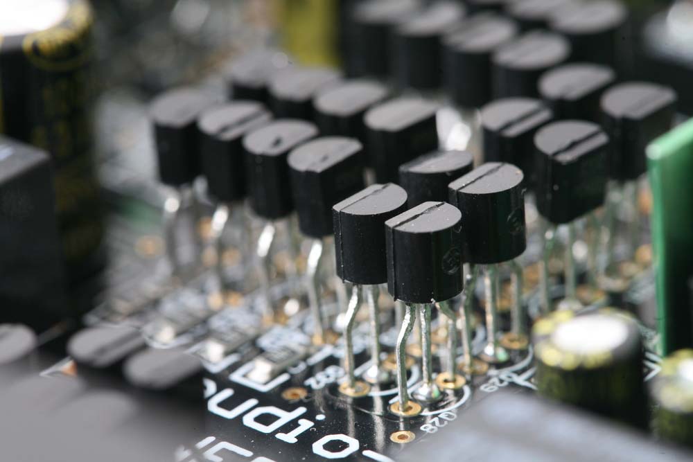 | Controls electrical behavior using an electric field. |
| Integrated Circuit | 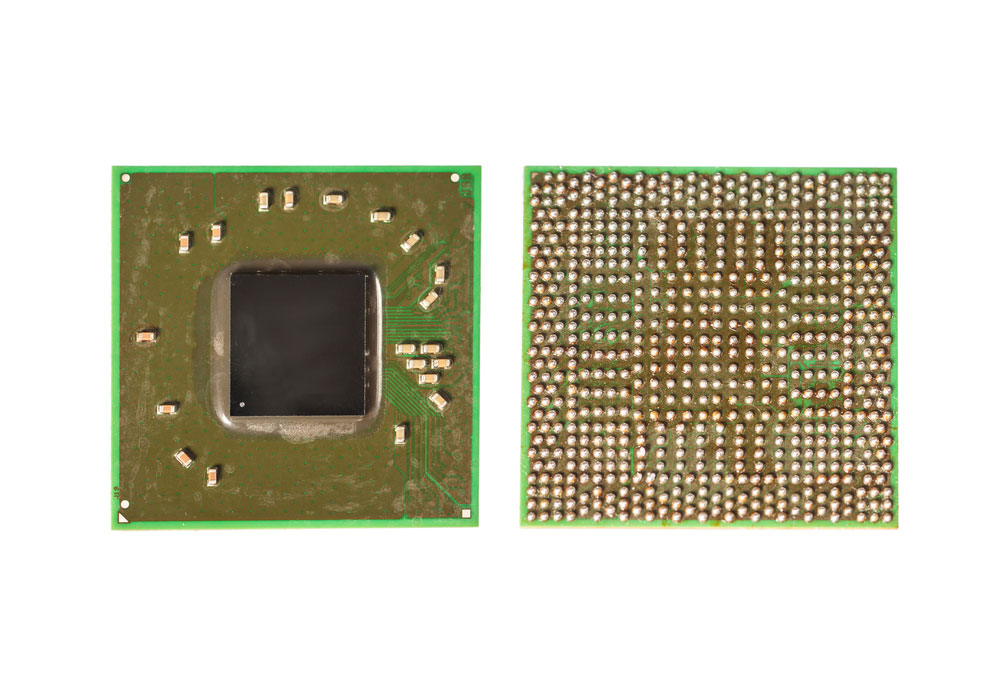 | A compact circuit with multiple electronic components integrated on a chip. |
| Potentiometers | 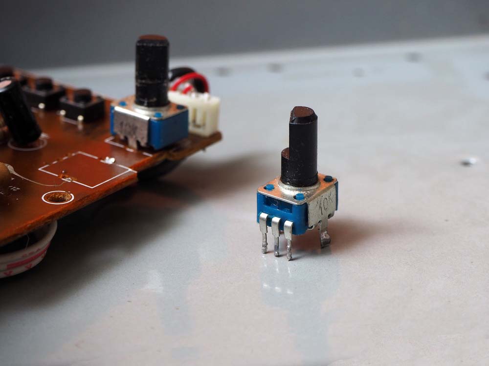 | Potentiometers are three-terminal variable resistors with a sliding contact that adjusts voltage, ideal for controlling audio volume. |
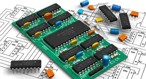
| Circuit Boards | 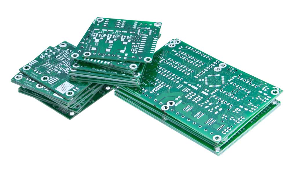 | The platform where electronic components are mounted and connected. |
| Switch | 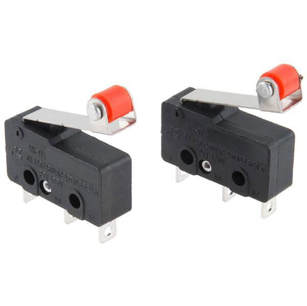 | Switches regulate the flow of electric current through circuits and require manual or physical input to cut or reconnect the power supply. |
| Connectors | 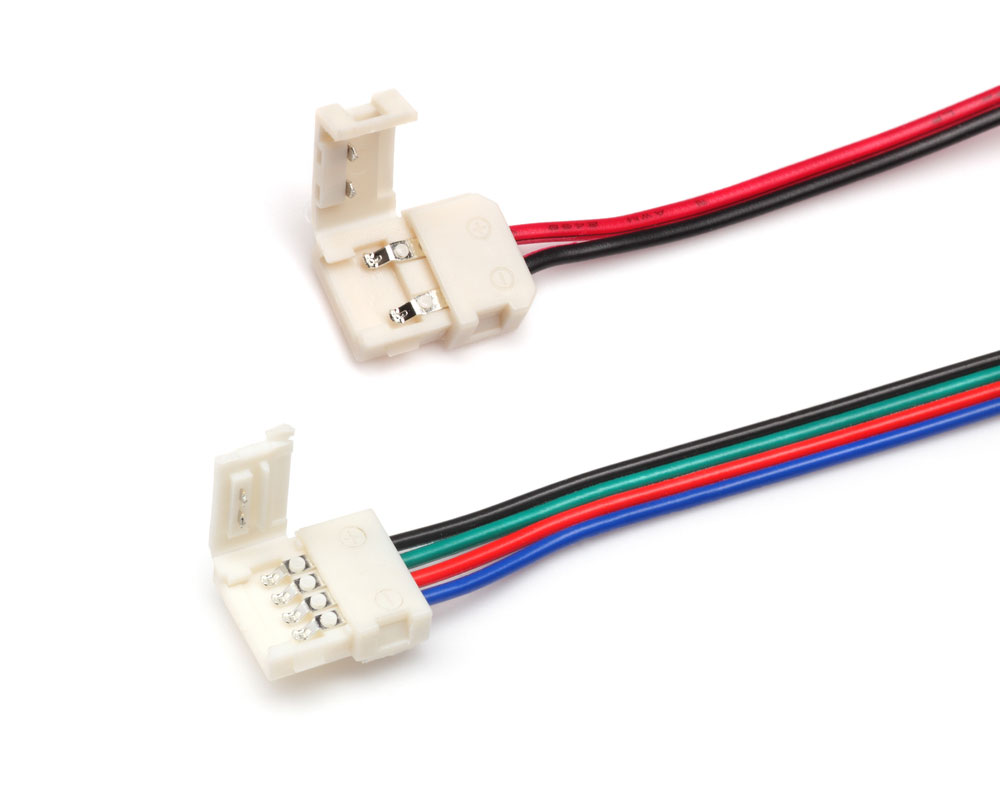 | Provide electrical connections between different components or devices. |
| Solder Mask | 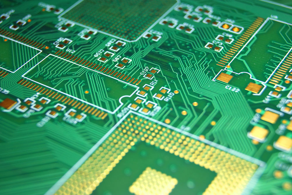 | Protective layer applied to the PCB to prevent oxidation and shorts. |
| Copper Layer | 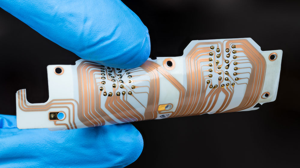 | Conductive layer on the PCB that forms the circuits and connections. |
| Varistors | 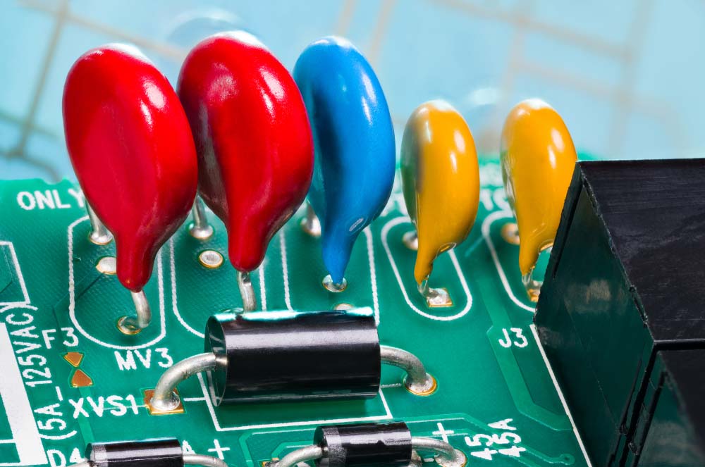 | Varistors are voltage-dependent resistors that protect circuits from spikes and surges. Their resistance decreases as voltage increases. |
| Thermistors | 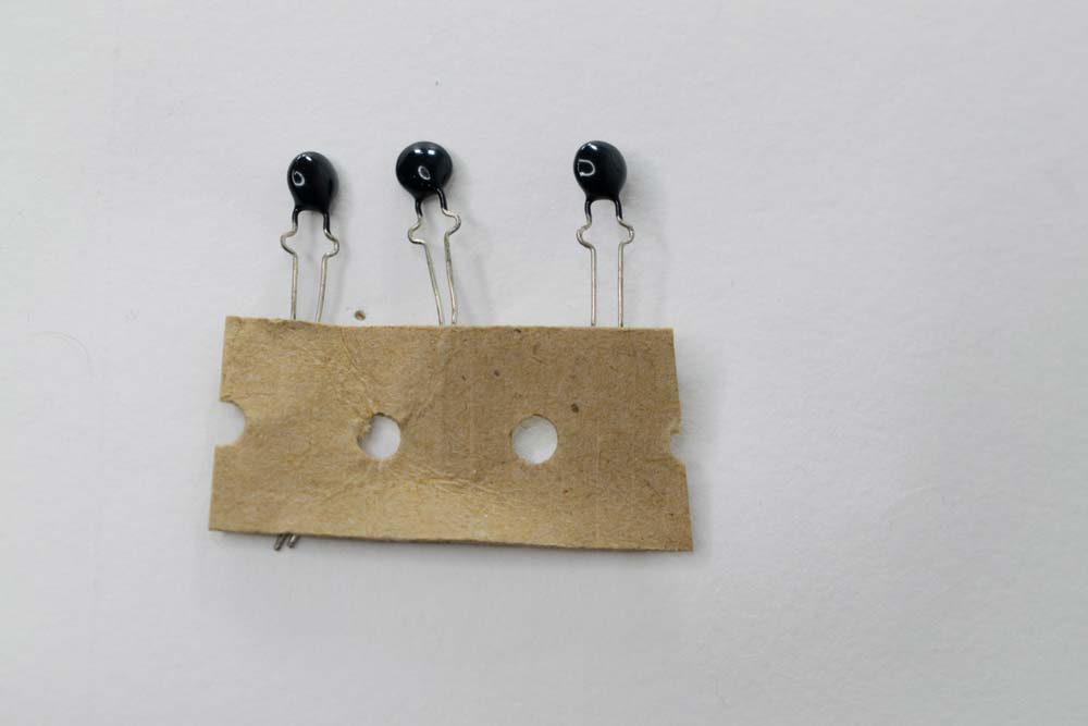 | Thermistors are variable resistors used as temperature sensors. Their resistance changes with temperature and can be NTC (decreasing resistance) or PTC (increasing resistance). |
| Resistor Networks | 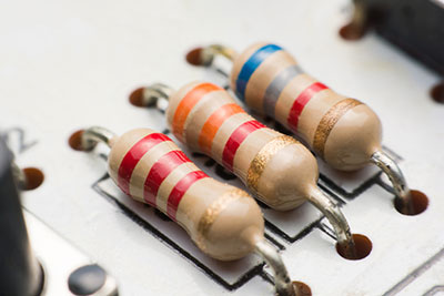 | Resistor networks group multiple resistors in one package, commonly used in digital circuits to manage current and voltage flow. |
| PCB Traces | 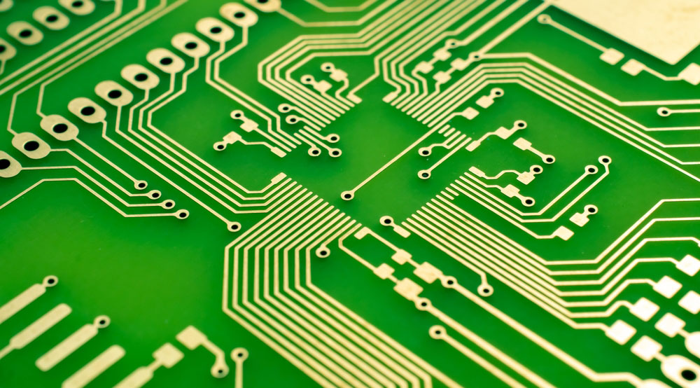 | PCB traces are conductive paths, usually made of etched copper, that transmit power and signals to components on the board. |
| Active Components | 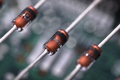 | Active components add energy to circuits, requiring external power for amplification and switching. Key types include operational amplifiers, microprocessors, transistors, and diodes, which are used for voltage amplification, processing, switching, and AC to DC conversion. |
| Voltage Regulators | 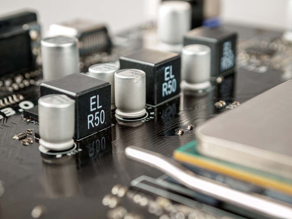 | Voltage regulators ensure stable output voltage. Key types include linear, switching, LDO, buck, boost, and charge pump regulators, each suited for different power and efficiency needs. |
| Optoelectronics | 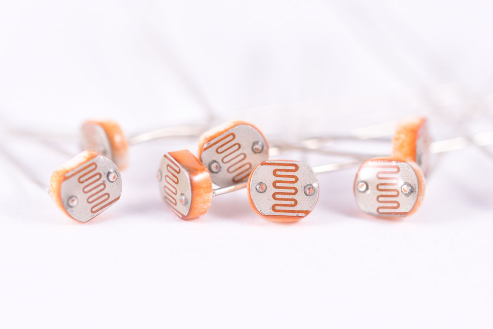 | Devices that convert light to electrical signals or vice versa, such as LEDs, photoresistors, and photodiodes. LEDs emit light when current flows in forward bias. |
How to Identify PCB Components?
Visual Identification
Visual identification is the first step in recognizing PCB components. By examining the size, shape, color, and markings on a component, you can often determine what they are and their function. Key points to consider include:
- Component Labels: Most circuit boards have printed labels or symbols next to the components, such as “R” for resistors, “C” for capacitors, “L” for inductors, “Q” for transistors, and “U” for integrated circuits.
- Color Codes: Resistors often use color bands to indicate their resistance value. Capacitors may have printed numbers indicating their capacitance.
- Shape and Size: Components like resistors, capacitors, and inductors have distinctive shapes. For example, resistors are cylindrical with color bands, while electrolytic capacitors are typically cylindrical with one flat end.
Using a Multimeter
A multimeter is an essential tool for testing and verifying the function of PCB components. It can measure resistance, capacitance, and voltage, assisting in identifying and confirming a component’s status. Here’s how to use a multimeter:
- Testing Resistors: Set the multimeter to measure resistance and touch the probes to both ends of the resistor. The reading should match the resistor’s color-coded value.
- Testing Capacitors: To check a capacitor, set the multimeter to the capacitance setting and connect the probes to the capacitor terminals. The reading should be close to the value printed on the capacitor.
- Testing Diodes and Transistors: Use the diode setting on the multimeter to test diodes and transistors. For diodes, check for continuity in one direction only. For transistors, test the junctions between the base, collector, and emitter.
Reference Materials
When visual identification and multimeter testing are insufficient, reference materials such as datasheets, circuit diagrams, and online databases can be invaluable. These resources provide detailed information about component specifications, pin configurations, and how they are used within a circuit:
- Datasheets: Available from manufacturers, datasheets provide detailed technical information about specific components, including electrical characteristics, pin layouts, and recommended usage.
- Circuit Diagrams: Schematics and diagrams help you understand how components are connected within the circuit, aiding in identification and troubleshooting.
- Online Resources: Websites and databases dedicated to electronics offer searchable component catalogs, cross-reference tools, and forums for discussing identification challenges.
Common PCB Component Designators
The table below lists commonly used PCB component designator codes:
| Designator | Component type | Designator | Component type |
|---|---|---|---|
| A | Separable assembly or sub-assembly (e.g. printed circuit assembly) | LS | Loudspeaker or buzzer |
| AT | Attenuator or isolator | M | Motor |
| ATT | Attentunator | MOV | Metal Oxide Varistor |
| BR | Bridge rectifier | MK | Microphone |
| BT | Battery | MP | Mechanical part (including screws and fasteners) |
| C | Capacitor | OP | Opto-isolator |
| CB | Circuit Breaker | P | Plug (most-movable connector of a connector pair), Plug connector (connector may have “male” pin contacts and/or “female” socket contacts) |
| CN | Capacitor network | PS | Power supply |
| D,CR | Diode (all types, including LED), thyristor | Q | Transistor (all types) |
| DL | Delay line | R | Resistor |
| DS | Display, general light source, lamp, signal light | RN | Resistor network |
| G | Oscillator | RT | Thermistor |
| J | Jumper or Jack | RV | Varistor, Variable resistor |
| L | Inductor | S | Switch (all types, including buttons) |
| F | Fuse | T | Transformer |
| FB | Ferrite bead | T | Thermocouple |
| FD | Fiducial | TP | Test point |
| FL | Filter | TUN | Tuner |
| G | Generator or oscillator | U | Integrated circuit (IC) |
| GN | General network | V | Vacuum tube |
| H | Hardware, e.g., screws, nuts, washers | VR | Voltage regulator (voltage reference), Variable resistor (potentiometer or rheostat) |
| HY | Circulator or directional coupler | X | Socket connector for another item not P or J, paired with the letter symbol for that item (XV for vacuum tube socket, XF for fuse holder, XA for printed circuit assembly connector, XU for integrated circuit connector, XDS for light socket, etc.) |
| IR | Infrared Diode | XTAL | Crystal |
| J | Jack (least-movable connector of a connector pair), Jack connector (connector may have “male” pin contacts and/or “female” socket contacts) | Y | Crystal or oscillator |
| JP | Jumper (Link) | ZD | Zener Diode |
| K | Relay or contactor | L | Inductor or coil or ferrite bead |
How to Place PCB Components?
Here are some component placement recommendations:
- Understand Mechanical Constraints: When designing a PCB, it is crucial to consider the enclosure in which the PCB must be mounted. Regarding the board’s dimensions and design, the placement of mounting holes and edge connectors must be known accurately.
- Consider Assembly Constraints: Before creating the circuit board, consult the manufacturer to understand how the board and components will be assembled and tested. The manufacturer needs to outline the assembly procedure and specify how much space is available on the board.
- Do Not Place Integrated Circuits Too Close: The recommended distance between each IC on the board is between 0.350 and 0.500 inches, allowing more space for larger ICs. When ICs are placed too close, there might not be enough room for routing the connecting traces, which requires time-consuming design reorganization.
- Use Standard Orientation for Components: This simplifies the installation, inspection, and testing process for the manufacturer. Similar components should face the same direction to avoid disrupting the soldering process, which could lead to some parts not being soldered at all, causing board shorts and open circuits. Integrated circuits always have a reference pin, regardless of their footprint or terminal count. Designers must ensure ICs are all oriented in the same direction to simplify the PCB layout and make the assembly process more straightforward. Consequently, placement errors are reduced, and assembly efficiency is improved. More generally, the rule is to solder comparable components (including passive components) in the same direction to maximize efficiency and minimize errors.
- Minimize Connection Routing: It is recommended to group parts together to reduce crossover and crisscrossing connections, leading to a simpler, less complex routing approach.
- Group Components by Function: Components with similar functions should be grouped. For example, converters, LDOs, and other similar devices that generate significant heat and high currents should all be placed in the same power management area. When using high-switching-frequency signals, analog and digital components, as well as power sections, should be separated. Furthermore, components generating electromagnetic noise or radiation need to be kept away from more sensitive signals. It also provides better control over return paths by classifying components based on their functional groups.
- Separate Different Areas from Each Other: Digital, analog, RF, and PCB areas containing power components should be separated from each other. By separating the various functional domains, crosstalk phenomena that threaten signal integrity between combined analog and digital signals can be prevented. The simplest way to prevent analog and digital traces from overlapping is to keep non-uniform components in different locations. Analog and digital sections must follow the same guidelines to prevent confusion.
- Keep Components Away from Heat Sources: MOSFETs, IGBTs, PMICs, and regulators generate substantial heat when used in high-power applications. It is generally best to keep other components away from power components, even if you add extra vias to aid heat dissipation. The same applies to heat-dissipating devices like operational power amplifiers.
- Create a Solid Ground Plane: As discontinuities can foster the onset of signal and power integrity issues, the ground plane should ideally remain uninterrupted. If a uniform ground plane cannot be maintained, extra care must be taken when positioning components near the discontinuity. For instance, high-speed signal transmission lines should not cross ground plane discontinuities, as doing so severs the signal’s return path. In addition to using a solid ground plane, avoiding excessive routing that might block the signal return path is another standard practice that helps create a secure and well-defined return path. To adequately protect control signals and reduce the chance of interference, it is advisable to also insert low-impedance links if the ground plane is already on an inner layer.
- What to Place Near the PCB Edge: Connectors, especially if they need to be secured with screws, must be placed near the PCB’s edge. This simplifies the board’s construction and installation and prevents cables from inadvertently contacting other PCB components.
- Leave Sufficient Space for Traces: Due to current trends, increasingly smaller PCBs are required in electronics, most notably in the wearable and portable device industries. The size of a circuit can only be reduced to a certain extent, and this optimal size must always be observed. Otherwise, routing all traces becomes nearly impossible. Therefore, when placing components, care must be taken to leave sufficient space on the PCB for copper traces to pass through, especially near components with many pins.
- High-Speed Signals: To facilitate easier trace routing, components handling high-speed signals must be grouped in one section of the PCB and placed close to each other. Short, straight traces are required to connect these signals. Decoupling capacitors must also be connected to the power ports of high-speed devices consuming significant current (e.g., CPUs, FPGAs, GPUs). The placement of these capacitors can be more challenging on digital boards or when components with BGA packages are present. To prevent oscillations on the power and ground signals and address any power integrity issues at the source, bypass capacitors must be positioned as close as possible to the VCC pin of the active component.
- Thermal Management: The heat generated by components during operation must be considered during placement. The PCB’s core material should be utilized for heat-dissipating components like CPUs to distribute heat evenly around the board. It is also important to pay attention to the path taken by the airflow to prevent the cooling of the hottest components from being hindered by the presence of larger components. Furthermore, it is best to immediately reserve adequate space for installing any heat sinks or other devices designed to enhance heat dissipation.
Fundamentals of Electronic Components Influencing PCB Layout
In its simplest form, PCB layout refers to the process of transferring a circuit from a breadboard to a permanent and stable physical state. Electronic circuits can be categorized into many groups, components, and types, as described below.
Categories of Electronic Circuits:
- Active Components – Active components rely on the system’s energy source. Active components are capable of supplying power to the circuit.
- Passive Components – Passive components cannot supply energy to the circuit. They cannot amplify signals as they do not rely on a DC power source like active components do.
Electronic Circuit Components:
The following are essential components of an electronic circuit. Here are some basic electronic circuit components you should familiarize yourself with when working with PCBs:
- The flow of electrons is called electronic current. Electrons move from the negative terminal to the positive terminal on a circuit board. Conventional current is considered to flow like positive current.
- Power Source: Regarding the power source, choosing the type most suitable for your device is crucial. You can choose between AC input and DC input based on where you plan to use the gadget.
- Electrical Load: An electrical load is more like an electrical component that uses power. It differs from power-generating sources like batteries or generators. Loads on a PCB include items like lamps and appliances.
Types of Electronic Circuits:
There are many kinds of electronic circuits. The most important among them are the following:
- Direct Current (DC): In a DC electronic board, current flows in only one direction. DC is commonly used for smaller PCBs.
- Alternating Current (AC): In an AC Printed Circuit Board (PCB), current flows bidirectionally while frequently switching direction. Besides its ability to travel long distances without significant energy loss, AC is also relatively simple to generate.
- Series Circuit: A series circuit is created by connecting components one after another in a single loop. Only one terminal serves as the means of connection between parts. A break in the chain ultimately causes the entire circuit to fail.
- Parallel Circuit: Contrary to a series circuit, a parallel circuit PCB requires positioning parts in different branches. The connection between individual components in a parallel circuit is made through both ends, albeit in different sections. When a connection breaks in a parallel circuit, only the affected branch is impacted.
How to Select PCB Components Based on Desired Functionality?
How to Identify Components Step by Step?
Like most things in life, breaking a task down into smaller parts can make identifying those components easier.
- Determine the Board’s Use: First, try to view the board as a whole. What does it do? Is it a daughterboard, a motherboard, or does it serve another purpose? Some boards are marked with codes that facilitate this. For example, the DMCB board shown below is the DOS Master Control Board for a GE Mark V system. This is a common acronym on GE boards. They can help with understanding.
- Identify Parts: Next, look for passive components such as capacitors and inductors. Don’t worry; images will be included later in this article. Next, look for potentiometers and resistors. They are often marked with ohm values.
- Locate Other Distinct Components: Oscillators (often cylinders or boxes denoted by X or Y), transformers (T), diodes (D), and relays (often marked as K) are further distinguishable components.
- Check for Fuses, Batteries, and Transistors: Now, examine the board to see if there are any fuses. Fuses are typically opaque or transparent tubes. Next, endeavor to locate any batteries or transistors.
- Identify Circuit Board Connectors: Note any circuit board connectors. The board might use connectors to link to other circuit boards, larger systems, or external components. The most popular connectors are backplanes, terminal blocks, pin headers and socket connectors, and jacks or plugs. There are many different types of connectors, and you could spend months learning about them.
- Identify Processors and Other Integrated Circuits: Finally, identify the board’s processor and other integrated circuits. Many ICs will have a label or ID containing the manufacturer and part number.
Some Important Suggestions for Selecting PCB Components.
- Bill of Materials (BOM) — Helpful for Virtual Parts: The primary function of the BOM will help you create a virtual PCB parts list when you need it. It is also useful for allowing the design department to review virtual parts. Power and ground signals might exist as virtual components. These components are not moved to the layout section; they will undoubtedly remain in the schematic environment. If a part is used solely for simulation, it appears in the virtual section; if not, replace it with one that has a footprint.
- Reference Designators — Check the BOM Data Report: The primary function of reference designators is to assist organization and review of the BOM by ensuring all items are quickly numbered. Ensure your BOM data is accurate and evaluate it. Before proceeding to the design stage, verify that all parts are present and nothing is missing.
- Basic Design Outline: Before committing to expensive prototyping, the design outline helps provide a general understanding of where components will be located. Furthermore, this will provide a basic grasp of part placement, necessary heights, and whether the overall plan can function completely and electrically.
- Need for a Suitable Ground Plane: Ensure your design first includes a proper ground plane and bypass capacitors. You will need suitable capacitors, with the correct size and frequency, depending on the PCB’s intended use. Furthermore, avoid using capacitors in the design haphazardly and insist on a robust, well-designed ground plane.
- Basic Schematic: Before committing to expensive prototyping, the design outline helps provide a general understanding of where components will be located. Furthermore, this will provide a basic grasp of part placement, necessary heights, and whether the overall plan can function completely and electrically. (Note: This point seems repetitive; original text duplication).
- Need for a Suitable Ground Plane: (Note: This point is repeated verbatim from above in the original text).
- Consider Footprints: When building a PCB, the use of a schematic is crucial. If you use a schematic, you can perform operations more easily. Understand how to maintain and repair PCB damage, as well as the installation location of each PCB.
- Follow Acceptable Grounding Practices: When designing a PCB, you need to follow some grounding rules. Grounding is crucial in your design process. Without a solid ground, you may not ensure clean signal transmission from one component to another. Some basic grounding practices include leaving no inputs floating, planning the ground before routing traces, and minimizing series vias in ground paths.
- PCB Soldering – Select the Correct Components: PCB soldering might seem like a simple process, but if performed improperly, you might produce a low-quality circuit board. In mass production, two commonly used soldering methods are wave soldering and reflow soldering. If you want an excellent board, be sure to select the appropriate equipment. Ensure the soldering iron and solder are of the best caliber. If you select incorrect components, your PCB will not work.
- Separate Leaded from Lead-Free Components: For a long time, leaded solder was the material of choice in electronics manufacturing and rework. However, in recent decades, environmental concerns and issues associated with lead-based products have increased. The project scope often determines whether to use leaded or lead-free components. However, according to recent government regulations, you may be required to choose lead-free components. Lead-free components are known to be safer for humans and the environment.
- Is Solder Mask Required?: The exposed portions of a printed circuit board or PCB pad are where components are mounted and soldered. Pads come in various forms and shapes depending on the component soldered to that location. Solder mask helps prevent potential flashover and electrical conductor tracking (current leakage between closely spaced conductors).
- Pad Design Must Match the Lead Configuration on the Component: It really is that simple. The component’s leads and the pad design must be compatible. To prevent unbalanced solder joints, ensure the pads closely match the lead configuration.
- Consider Component Package Options: Will you choose Surface Mount Technology (SMT) or Plated Through-Hole (PTH) components? Component selection can be altered during the design phase. Deciding during the design stage which components will use SMT and PTH can benefit the overall organization of the PCB. When you consider component selection, aspects like component pricing, availability, component area density, and power dissipation come into play, which will influence your design.
- Review Unused Gates: To prevent inputs from floating, most unused gates should generally have their inputs tied to a signal (e.g., VCC or GND via a pull-up/pull-down resistor, as appropriate). Ensure you check all unused gates to guarantee that, if necessary, unconnected inputs can be properly terminated. If inputs remain floating, the entire system may sometimes malfunction.
Common Issues with Circuit Board Components
Circuit board components can encounter various problems, often leading to device failure. Understanding these common issues can help you troubleshoot and resolve problems more effectively.
Identifying Faulty Components
Faulty components are a primary cause of circuit board failure. Common signs of component failure include:
- Burn Marks: Indicate overheating or short circuits. Components like resistors and ICs may show visible signs of damage.
- Bulging or Leaking Capacitors: Electrolytic capacitors may swell or leak electrolyte when failing, often due to overheating or aging.
- Cracked or Damaged Parts: Physical damage, such as cracks in resistors or transistors, can cause components to malfunction.
- Heat-related failures are particularly common in high-power circuits, making effective PCB thermal management essential for preventing component damage and ensuring long-term reliability.
Troubleshooting Techniques
Effective troubleshooting requires a systematic approach to diagnose problems:
- Visual Inspection: Start by visually inspecting the board for obvious signs of damage, such as burn marks, corrosion, or loose connections.
- Component Testing: Use a multimeter to test individual components, comparing readings to expected values.
- Circuit Tracing: Follow the circuit paths to identify potential issues with connections or component interactions. Use the circuit schematic as a reference.
Replacement and Repair Tips
When a component is identified as faulty, replacement or repair may be necessary:
- Component Sourcing: Ensure you source the correct replacement component, matching specifications such as resistance, capacitance, and voltage ratings.
- Safe Removal: Use appropriate tools, such as a soldering iron and desoldering pump, to safely remove the faulty component without damaging the board.
- Proper Installation: When installing the new component, ensure correct orientation and secure soldering to maintain reliable connections.


0 Comments