
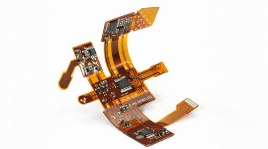
Flexible Printed Circuit Board (FPC), or Flexible PCB / Flex Circuit, lets electronics bend, fold or conform to non-flat shapes. When every millimeter and gram counts—wearables, foldables, medical devices—this is often the only realistic solution.
What Is a Flexible PCB & Why It Solves Your Challenges
An FPC is built on bendable substrates like polyimide (PI) or PET instead of rigid FR-4. It delivers thin, lightweight, space-saving circuits that rigid boards cannot achieve. In tight enclosures or products with movement, flexible boards reduce connectors, lower assembly complexity and boost reliability.
How Flexible PCBs Deliver Both Flexibility & Reliability
They work by combining copper traces on flexible film, protected coverlayers, and stiffeners at load-bearing sections. Design rules include ensuring sufficient bend radius, avoiding vias or pads in active flex zones, using curved traces, and choosing copper and adhesive materials that resist fatigue and environmental stress.
Different Types: Single-Layer, Multilayer & Rigid-Flex Options
Basic single-layer FPCs are cost-effective and simple. Double- or multilayer boards enable more signal routing. Rigid-flex combines rigid parts for components with flexible areas for connections. Each adds cost and complexity but expands capability and durability.
Key Materials to Choose for Durability
- Substrates: Polyimide for high temperature and fatigue resistance; PET for lower cost but lower endurance.
- Copper foil types: Rolled-annealed offers better fatigue life than electrodeposited copper.
- Coverlay & adhesives: Must survive soldering heat and resist moisture.
- Stiffener plates: Reinforce component pads or connectors to avoid mechanical failure.
Advantages vs Challenges You’ll Face
Advantages: Flexibility, weight reduction, fewer connectors/flat ribbon cables, better fit in compact or moving assemblies.
Challenges: Higher cost per unit for complex designs, strict design and manufacturing tolerances, vulnerability under repeated bending, repair is difficult.
Rigid-Flex vs Flex vs Rigid: Practical Comparison
If you design a foldable medical scanner: a rigid board adds bulk and costs, a flex board saves space but needs careful protection; rigid-flex gives structural stability and reliable component support—in many cases the gold standard if budget allows.
Common Failure Modes & How to Prevent Them
- Copper trace fatigue: caused by too tight or frequent bending—mitigate with proper radius and trace layout.
- Delamination: adhesives failing under heat/humidity—select suitable adhesives and test.
- Pad lifting or joint cracking: stress at connector or solder joint zones—use stiffeners and relieve stress.
- Coverlay cracking or separation: often around edges—careful edge design and strong coverlay materials help.
Real-World Case Studies
Here are some projects we handled:
- A wearable health tracker: FPC used as connection between band and main module; after 20,000 flex cycles still no breaks.
- Foldable display hinge: rigid-flex structure supporting display and flex-to-rigid transition with minimal stress.
- Portable medical device: embedded flexible cable shielded against EMI, reducing interference by over 10 dB.
Design Guidelines Engineers Wish They Knew Earlier
- Compute bend radius: ≥ 6× thickness for static bends; ≥ 10× for dynamic or repeated flex.
- Don’t place vias or pads in active flex areas.
- Use curved traces instead of sharp angles.
- Reinforce solder pads or connectors with stiffener plates.
- Select materials with lab-tested performance: thermal cycling, moisture resistance, mechanical fatigue.
Manufacturing Process & Quality Controls We Implement
From prototype to mass production, steps include Gerber file submission → DFM review → sample build → environmental and mechanical testing → full tooling → final inspection. We follow IPC-6010, UL, RoHS; for medical, ISO 13485 applies. All boards are 100% electrical tested; multilayer boards get X-ray if needed.
What Drives Cost in Flexible PCB Procurement
- Materials: substrate type, copper thickness, coverlay quality, number of layers.
- Design complexity: layer count, trace density, bend radius demands.
- Quantity: small batch = higher unit cost; large orders spread setup and testing costs.
- Testing & certification: environmental, mechanical, fatigue, possibly regulatory bodies.
How to Choose a Supplier from Factory Level
Here’s what we always check before picking an OEM:
- Ask for previous FPC or rigid-flex board samples and their measured life under bend / heat / moisture.
- Confirm certifications: IPC, ISO 9001, ISO 13485, UL, etc.
- Verify production equipment: laser drilling, impedance control, bending fatigue test rigs.
- Assess lead times, batch consistency, after-sales support.
Final Checklist Before You Place the Order
- Clear stack-up drawings and bend/flex zones defined.
- Material data sheets supplied for all layers, adhesives, copper, coverlay.
- Test reports for bend cycles, thermal/humidity cycles.
- Sample physical inspection: edges, solder pads, flex zones for warping or defects.
- Packaging and transportation method to avoid damage in transit.
- Payment terms, warranty or return policy spelled out.
FAQ
Q1: How many flex cycles can a typical FPC survive?
It varies—cheap PET single-layer may fail after a few thousand bends; a well-designed polyimide FPC with correct coverlay and stiffeners can endure tens of thousands of bends under lab conditions.
Q2: How much more expensive is rigid-flex PCB compared to simple flexible board?
Rigid-Flex often costs 2-3× higher per unit due to complexity in rigid sections, lamination, hybrid stack-ups and more rigorous testing.
Q3: What minimum bend radius should I design for?
For static bends: at least 6× board thickness; for dynamic/frequent motion applications: aim for 8-10× thickness, sometimes more depending on material fatigue.
Q4: Does moisture degrade flexible PCBs significantly?
Yes. Moisture causes adhesive layers to swell or lose bond strength, leading to delamination. Use moisture-rated materials and perform thermal/humidity cycling tests.
Q5: When is rigid-flex the preferred approach?
Whenever components need mounting (connectors, mounted ICs) in rigid areas, but flexible connections are necessary. Critical in medical, aerospace, foldable devices.
Q6: What certifications should a reliable supplier hold?
Look for IPC standard certifications, ISO 9001, UL. If device is medical: ISO 13485. For automotive: look for relevant automotive quality system certificates.
Q7: What are frequent issues with coverlay material?
Common failures include cracking around edges, separation under thermal stress, peeling off due to poor adhesion or incompatible adhesives.
Q8: Are stiffeners always needed?
Not always. But when connectors or heavy components are involved, stiffeners prevent mechanical fatigue and prolong life. The additional cost is typically offset by fewer failures.
Q9: How to Inspect Board Quality Before Large Orders?
Request samples, check bend zones under microscopes, test line widths and copper thickness, review test reports, examine for delamination or irregularities.
Q10: How should flexible PCBs be packaged and shipped internationally?
Flat and secure packaging is vital—use stiffeners, anti-static bags, humidity control, clear documentation for customs. Rough handling can damage flex zones irreversibly.
Conclusion: Key Technical, Selection & Procurement Advice
The heart of a rugged flexible PCB lies in precise material and structural design: bend radius, fatigue resistance, quality of copper and protective layers are non-negotiable. When you pick materials and suppliers wisely, even budget builds can achieve high reliability.
Select based on real usage environment—heat, humidity, motion. Prioritize supplier experience, test data, certifications. A factory with OEM/ODM strength, stable output and transparent quality records is your best partner.
If you are looking for dependable OEM manufacturing, ODM production, prototype development, mass production or custom engineering solutions, feel free to contact our engineering team for technical support and quotation services.
Email: sales@pcbtry.com


0 Comments