
A drone PCB is the core of every flying system. It carries the signals, power paths, control logic, and sensor links that keep a UAV stable in the air. When a drone loses balance, responds slowly, or shows unstable video, the issue often relates to the PCB inside the frame. For engineers and product teams building UAV platforms, understanding the structure and behavior of a drone PCB board brings more predictable flight performance and fewer field failures.
At Thindry Circuit, we work with companies in commercial drones, industrial UAVs, mapping drones, FPV systems, and inspection platforms. Our team supports full drone pcb design and manufacturing with controlled impedance, HDI structures, and stable power routing. This guide explains how drone PCBs work from schematic to layout, and why proper engineering matters so much for modern UAV products.
What Is a Drone PCB?
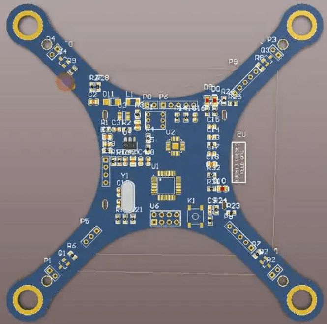
A drone PCB is a printed circuit board designed to manage power delivery, signal routing, sensor input, and motor control inside an unmanned aerial vehicle. Unlike regular PCBs, a UAV PCB must stay light, compact, and stable under vibration. It often integrates the flight controller, IMU sensors, and ESC interfaces in one compact board.
A typical drone pcb board includes:
- Microcontroller or SoC
- IMU (gyro + accelerometer)
- Power distribution network
- Motor driver paths
- GPS / communication module
- Camera or gimbal control pins
- Voltage regulation circuits
- Debug and calibration ports
Each part influences the safety and responsiveness of the UAV. That is why material choices, copper weight, and PCB stack-ups are crucial for stable performance.
What Is a Drone PCB?
Key Types of Drone PCB Boards
Modern drones use several boards working together. Each has a different design purpose.
- Flight Controller PCB
This is the “brain” of the UAV. It reads IMU data and stabilizes flight. The layout must isolate sensor noise and keep high-frequency signals clean.
- ESC Power PCB (Motor Control Board)
This part drives the motors. A pcb motor drone board uses heavy copper, strong MOSFET drivers, and thermal areas to handle high current.
- GPS / Communication PCB
This board manages long-range signals, low-noise amplifiers, and RF antennas. Impedance control and grounding guard lines are essential.
- Camera & Gimbal PCB
Transmits video, stabilizes movement, and manages tilt/roll. Architects must separate power noise from sensor lines.
- Battery and Power PCB
Handles charging, balancing, and battery protection. High reliability is required.
- Sensor PCB
Carries ultrasonic sensors, barometer sensors, optical flow, or LiDAR modules.
A typical consumer drone uses four to six PCB boards in one system. Industrial UAVs may use more.
What Does a Drone PCB Schematic Include?
The drone pcb schematic is the blueprint of the entire control system. It defines every connection before the layout stage.
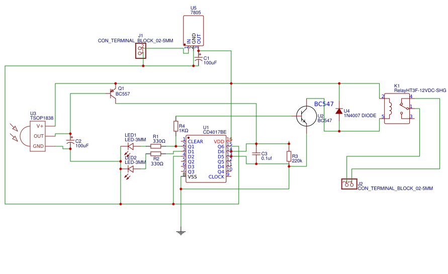
A clean schematic contains:
- MCU or SoC core
- IMU sensor block
- RF module block
- ESC signal block
- Power rails (5V, 3.3V, VBAT)
- Buck/boost converters
- Connectors for motors, camera, GPS
- Debug/UART/SWD pins
- Grounding and filtering components
- Telemetry paths
- Fail-safe circuits
A good schematic reduces layout mistakes and improves long-term reliability. Noise-sensitive blocks stay well-connected to clean ground. High-current ESC blocks have clear routing paths. This level of organization gives the drone more stable behavior in flight.
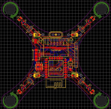
Drone PCB Design Consideration
Designing a drone PCB is more than placing parts on a board. Every trace, every loop, and every copper zone affects how the UAV behaves in the air. A drone depends on fast responses and stable signals. That’s why engineers must consider electrical, thermal, and mechanical needs at the same time.
Drone PCB Design Consideration
1. Power Integrity
The motors draw large current during takeoff and fast movement. These sharp peaks can drop voltage across the board if the power network is weak. Use solid copper areas for VBAT and ground. Keep the main power path short. Add local capacitors near ESC inputs. These steps prevent sudden drops that may cause flight controller resets.
2. Clean Grounding for Sensors
Gyro and accelerometer sensors react to tiny vibrations. Noise from power lines or motor drivers can distort readings. Create a stable ground plane. Keep analog and digital grounds connected at one point. Leave noisy circuits away from the IMU area. This keeps sensor readings stable and improves drone balance.
3. EMI Control for GPS and Communication
GPS is very sensitive. Even small interference can weaken the satellite lock. Use controlled-impedance traces for RF sections. Add guard rings around antennas. Keep switching regulators far from the GPS module. A quiet RF zone improves signal quality and keeps the drone on course.
4. Good Heat Flow Around ESC and Drivers
ESC chips, FETs, and regulators generate heat during flight. If the board traps this heat, parts will age faster. Use thermal vias under power components. Spread heat by adding copper plates. These simple steps lower part temperature and extend the PCB lifespan.
5. Stable Signal Paths
Drone pcb design needs clean routing for high-speed signals. Keep differential pairs for video or camera lines short and straight. Avoid running small signal traces near high-current paths. Use matched lengths where needed. These steps keep signals clean and stable, which is important for camera clarity and control accuracy.
A well-designed drone PCB feels smooth in the air. Motors respond faster. GPS locks quicker. Sensors read more accurately. Good design brings better flight experience for both users and developers.
What Is VCC in a Drone PCB Board?
VCC is the positive supply voltage line. It is the main power source for sensors, MCU, and communication systems.
A drone usually uses several voltage rails:
- VBAT: Direct battery output
- 5V: For camera, GPS, LED, video TX
- 3.3V: For MCU and IMU sensors
- VCC: General logic supply depending on design
Stable VCC is vital. If this rail drops during motor spikes, the flight controller may reboot mid-air. Good pcb motor drone design prevents this by using:
- Thick tracks
- Short power loops
- Large bypass capacitors
- Low-noise regulators
These small details protect the UAV from sudden shutdowns.
How to Choosing the Right Layer Count for a Drone PCB?
Selecting the correct PCB layer count is one of the most important decisions in UAV electronics design. The number of layers influences signal quality, thermal balance, structural strength, and final system weight. UAV systems run mixed-signal environments, high-current motor loads, and sensitive RF circuits; therefore, layer planning must follow clear engineering logic.
- 4–6 Layers for Consumer UAV Platforms
Photography drones, hobby quadcopters, and lightweight FPV platforms usually fall within the 4–6-layer range.
These layers support:
- Basic flight-control logic
- GPS and IMU interfaces
- 2.4 GHz / 5.8 GHz RF paths
- Standard video transmission
- Remote-control links
With proper stack-up planning, even a 4-layer board can achieve stable isolation between dual-band RF paths.
- 8–12 Layers for Industrial and High-Payload UAVs
Logistics drones, mapping UAVs, and inspection platforms often require more layers to support high-speed interfaces such as:
- Gigabit Ethernet
- PCIe
- High-resolution camera interfaces
- Multiple sensor buses
- Redundant power rails
More layers allow better signal separation, tighter impedance control, and improved grounding for stable long-range flight. UAV frames—especially carbon-fiber structures—place strong mechanical demands on the PCB. A typical drone PCB thickness ranges from 1.2 mm to 1.6 mm to match frame stiffness and mounting geometry.
Common Failures Seen in Drone PCB Boards
1. Solder Joint Fatigue From Vibration
UAV motors produce continuous vibration at 100–200 Hz. Over time, solder joints—especially on IMU, barometers, and connectors—can form micro-cracks.
Typical failure zones include:
- IMU QFN/LGA pads
- Battery connectors
- ESC-to-motor solder pads
Selecting wider pads and using corner bonding for LGA packages reduces fatigue.
2. MOSFET Thermal Overstress in ESC Stages
ESC boards switch at 24–48 kHz, producing heat concentrated around FETs. If copper weight or thermal vias are insufficient, junction temperatures rise above safe margins.
This leads to:
- Increased Rds(on)
- Lower efficiency
- Accelerated MOSFET aging
Engineers often model heat flow using thermal simulations to size copper pours correctly.
3. Via Barrel Cracking
Power cycles and high current spikes cause stress inside plated via barrels.
Common when:
- Via aspect ratio > 10:1
- Tg is too low
- Current density is uneven
Using via stitching and filled vias reduces risk in high-current areas.
4. Copper Trace Delamination
Thin traces near motors or battery input can delaminate when current spikes exceed design limits.
Risk rises when:
- Trace width < required amperage chart
- No thermal relief
- No additional copper reinforcement
This is why wide pours and multi-layer copper balancing are essential.
5. Environmental Corrosion
Outdoor drones often deal with moisture. If conformal coating is missing or applied poorly, exposed copper near sensors or MCU I/O pads may oxidize.
This causes:
- Increased resistance
- Sensor drift
- MCU brownouts
UAV boards often use ENIG finish plus urethane or silicone conformal coating for added protection.
3 Mistakes Engineers Should Avoid
Mistake 1 — “More Layers Always Improve Performance”
A well-designed 6-layer board can outperform a poorly structured 8-layer board.
Symmetry, grounding strategy, and controlled impedance matter more than the layer count alone.
Mistake 2 — Ignoring RF Loss at 5.8 GHz
High-frequency video links require low-loss materials.
Standard FR-4 may cause excessive attenuation, leading to shorter transmission range or unstable video.
Mistake 3 — Relying Only on Simulation
Real UAVs experience:
- Doppler effects
- Rapid air-flow changes
- Frame-based vibrations
- Dynamic RF reflections
Why Choose Thindry Circuit for Drone & UAV PCB Projects?
UAV electronics need precise stack-up planning, tight impedance control, and stable power handling. Thindry Circuit supports these technical needs with engineering depth and controlled manufacturing processes tailored for UAV systems.
We assist with:
- HDI with microvias and via-in-pad
- High-Tg FR-4 laminates
- 2–4 oz copper for ESC power stages
- Rigid-flex architectures for gimbals and antennas
- Controlled impedance fabrication for RF and FPV systems
- X-ray for BGA and LGA IMU joints
- AOI for dense FC layouts
- Functional testing for ESC/MCU power rails
- Impedance verification for RF paths
- Tight-pitch QFN/LGA IMUs
If you are interested in drone PCB manufacturing, you are welcome to contact us.


0 Comments