
A keyboard is a user-operated device and in many cases, also prone to serious malfunctions. It consists of a logic circuit board (PCB), a key switch array, a case, and a wired or wireless module. Even if the PCB is securely fixed inside the keyboard case, it can still develop faults that require repair to remain functional.
This article outlines a universal method for repairing keyboard PCBs, providing guidance for efficiently fixing faulty keyboard PCBs.
Repair vs. Replacement: What’s the Difference?
Repair is additional work for PCB manufacturers, requiring extra resources. We always recommend attempting simple, quick repairs first. For major defects that are more time-consuming and costly, repair is not advised. In such cases, replacing the entire product is more convenient. If the PCB’s main components are severely damaged or traces are extensively burnt, it’s best to scrap the faulty PCB.
Routine Diagnostic Procedures Before Repair
Pre-repair diagnostics are crucial because accurately identifying the problem avoids unnecessary repairs and reduces risk. By systematically observing symptoms, gathering information, and performing tests, the root cause can be effectively pinpointed. This meticulous approach ensures efficient and safe repairs, laying the foundation for a successful repair strategy. The first step in learning how to repair a keyboard PCB is to follow a structured diagnostic procedure.
- Clearly Identify and Describe the Problem
Analyze and clearly describe the issue by observing the damage. For example, which key is unresponsive, what is the status of LED indicators, broken traces, damaged or lifted pads, component failure, solder joint issues, corrosion, damaged keyboard connectors, or firmware problems, etc., could all cause keyboard PCB failure. Understanding how to repair a keyboard PCB helps determine which areas to focus on in this step. - Visual Inspection
A careful visual inspection can reveal many critical faults on the PCB. Modern PCBs have increasingly complex structures and more components. Use a magnifying glass to inspect the PCB, ensuring it appears intact. Any signs of burning, physical damage, solder defects, or missing components clearly indicate the extent of the keyboard PCB’s damage. This step is crucial for effectively repairing the keyboard PCB. - Connectivity and Continuity Check
If the visual inspection is satisfactory, proceed with functional checks. Confirm whether the keyboard connects properly and if there is any damage at the connection ports. A multimeter can be used to check continuity along the PCB circuits. Any open circuits indicate damage in specific sections, which will guide the keyboard PCB repair process. - Key, Switch, and All Component Checks
A keyboard PCB consists of a series of switches and a closed circuit. A group of functionally similar keys interacts through specific switches. Carefully inspect each switch component and its circuit for defects. Each electronic component needs its characteristics checked. The keyboard circuit sends out signals to check the response of the pressed key. An abnormal response indicates a fault in the PCB. - Firmware/Configuration Check
Some current keyboard models support firmware checks and upgrades. In special cases, the core firmware of the keyboard PCB might be corrupted. You can find the current firmware version on the silkscreen or in the technical datasheet. Compare the internal firmware with the standard version. If any changes in the firmware or configuration are detected, take necessary actions. This final step is also closely related to how to repair keyboard PCB faults caused by software issues.
Detailed Repair Steps
Step 1: Safety Preparation and Preliminary Diagnosis
Before starting any repair, ensure you prepare the following:
- Disconnect: Unplug the keyboard from the computer to ensure it is completely powered off.
- Prepare Tools:
- Screwdrivers (for disassembling the keyboard)
- Multimeter (crucial for checking circuit continuity)
- Soldering iron, solder wire, desoldering pump/solder wick
- Tweezers
- Magnifying glass or phone macro mode (for inspecting fine details)
- Isopropyl alcohol and cotton swabs (for cleaning)
- Identify the Fault Phenomenon:
- Complete Failure: The entire keyboard is unresponsive.
- Partial Failure: A specific row, column, or area of keys is unresponsive.
- Single Key Failure: Only a few or one key is unresponsive.
- Key Chattering/Ghosting: Pressing one key triggers multiple keys.
Different fault phenomena point to different possible causes, helping you narrow down the scope of investigation.
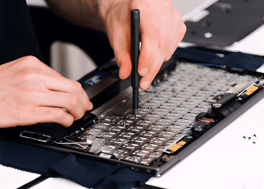
Step 2: Disassembly and Visual Inspection
- Disassemble the Keyboard: Carefully remove the keycaps, then unscrew all the screws on the bottom case to separate the upper cover from the PCB. Be aware of hidden screws under feet or labels.
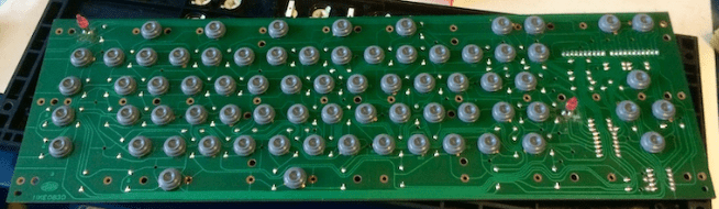
- Carefully Visually Inspect the PCB: Under good lighting, use a magnifying glass to carefully inspect both sides of the PCB, looking for:
- Burnt or Damaged Components: Look for resistors, capacitors, or diodes that are charred, cracked, or bulging.
- Broken Traces: Check if the copper traces have scratches or breaks.
- Corrosion or Stains: Check for signs of liquid spills causing trace corrosion or short circuits.
- Cold/Cracked Solder Joints: Inspect the solder joints of the main controller chip, diodes, and switches. They should be shiny and full. Cold solder joints are often dull, cracked, or ball-shaped.
- Solder Bridges: Check if there is excess solder causing shorts between solder points.
Step 3: Systematic Troubleshooting and Repair
Choose the following methods based on the fault phenomenon.
Scenario 1: Single or Few Keys Failure
This is usually due to the key’s switch or its corresponding circuit node.
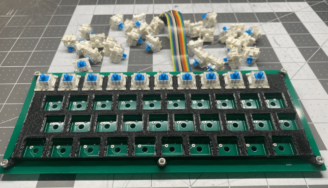
- Cleaning and Switch Replacement Method (Simplest)
- If the keyboard is hot-swappable, directly replace the faulty key’s switch with a known good one and test if it works. If it does, the original switch was bad; replace it.
- If it’s not hot-swappable, use the multimeter’s continuity mode. Place the probes on the two pins of the switch and press it. Listen for a “beep”. No sound indicates a faulty switch, which needs to be desoldered and replaced.
- Check the Diode
- Each key usually has a diode to prevent ghosting. If a specific key fails, its corresponding diode might be damaged.
- Test with a Multimeter: Set the multimeter to diode test mode. A normal diode will show a reading in the forward direction (0.4V-0.8V) and open circuit (OL) in reverse. If it conducts in both directions or neither, the diode is bad and needs replacement.
- Check PCB Traces
- Use the multimeter’s continuity mode. Place one probe on one solder pad of the faulty key and trace the circuit path with the other probe (may require checking PCB layout) until you find the break. Breaks often occur where the PCB has been bent or impacted.
- Repair Broken Trace:
- Scrape Off Solder Mask: Gently scrape off the green solder mask on the copper trace at both ends of the break using a blade, exposing the metal.
- Tin the Exposed Copper: Apply a little solder to the exposed copper using the soldering iron.
- Jumper Wire: Take a small piece of thin wire (e.g., enameled wire or headphone wire) and solder it across the broken ends to connect the circuit. Finally, secure it with hot glue or solder mask.
Scenario 2: Entire Row, Column, or Area Failure
This usually means the common line for that row or column is broken.
- Understand the Matrix Circuit: Keyboard keys are arranged in a matrix of rows and columns. The main controller scans each row sequentially and reads the state of each column to determine which key is pressed.
- Locate the Faulty Row/Column: You can measure to find which row and column the faulty keys belong to.
- Trace with a Multimeter:
- Find the pinout of the main controller chip (may require searching online for the keyboard’s PCB schematic).
- Using the continuity mode, start from a key pad in the faulty area and trace back to the corresponding pin on the main controller chip to see where the line is broken.
- Use the “jumper wire” method to repair the broken row or column line.
Scenario 3: Complete Keyboard Failure
This problem can be more serious, often related to the main controller, fuse, or USB interface.
- Check the USB Interface
- Visually inspect the USB port for looseness, broken solder joints, or bent pins.
- Use the multimeter’s continuity mode to check the connection of the USB data lines (D+, D-) and power lines (VCC, GND) to the PCB.
- Check the Main Controller Chip
- Visual Inspection: Check the main controller chip pins for cold joints or solder bridges.
- Measure Voltage: Power the keyboard. Using the multimeter in DC voltage mode, place the black probe on ground (USB shield or the negative leg of a large capacitor) and gently touch the VCC pin of the main controller with the red probe. Check for +5V. If not present, check the power supply line.
- Check the Crystal Oscillator: If there is a crystal oscillator (a metal component) near the main controller, it provides the clock signal. A damaged crystal can cause the controller to malfunction. This requires an oscilloscope for accurate judgment, but under amateur conditions, try gently reflowing the solder on the crystal’s two pins.
- Check the Fuse
- Many keyboard PCBs have a small fuse (may be labeled “F” or “FUSE”) near the USB power input.
- Measure it with the multimeter’s continuity mode. If there’s no continuity, the fuse is blown. You can temporarily bridge it with a thin wire (for emergency use), but it’s best to replace it with a fuse of the same specification.
Step 4: Soldering and Reassembly
- Soldering Techniques:
- Use an appropriate temperature (around 350°C typically) to avoid damaging pads or components with prolonged heat.
- Use flux when soldering for shinier, stronger solder joints.
- When removing components, use a desoldering pump or solder wick to clean the solder from the holes.
- Testing:
- Before full reassembly, connect only the PCB and USB cable to the computer.
- Use metal tweezers to short the two solder pads of a faulty key, simulating a key press. If the computer registers input, the PCB fault is repaired, and the problem lies with the switch.
- Alternatively, use online keyboard testing software to check all keys.
- Reassembly: After confirming all functions work correctly, reassemble the keyboard case and keycaps.
Summary and Recommendations
| Fault Phenomenon | Most Likely Cause | Repair Method |
|---|---|---|
| Single Key Failure | Switch failure, diode failure, damaged pad | Replace switch/diode, jumper wire |
| Row/Column Failure | Broken row/column trace, cold solder on MCU pin | Jumper wire to connect break, reflow MCU solder |
| Local Area Failure | Damaged common line or via in that area | Jumper wire connection |
| Complete Key Failure | USB interface, fuse, main controller chip, crystal | Check and replace damaged components |
| Key Chattering/Ghosting | Diode failure, dirty PCB short, MCU fault | Clean PCB, replace diode |
If the above steps cannot resolve the issue, it is likely that the main controller chip itself is damaged. This is extremely difficult for amateurs to repair, and replacing the entire PCB or keyboard may be necessary.
Best Practices and Preventive Measures
- Always follow all safety and ESD (Electrostatic Discharge) precautions when handling PCBs. Turn off power before operating on the PCB for repair.
- When replacing parts, use compatible and quality-qualified components. Inappropriate parts often affect product reliability and functionality.
- Mechanical parts of the keyboard assembly must be handled carefully. Operations like screwing, replacing key springs, and other components should follow correct procedures.
- For optimal soldering results, the soldering iron must have a controllable temperature range.
- Small components are inherently fragile; improper handling may cause greater damage. Therefore, always handle the PCB gently.
- Standard tools must be used during testing and troubleshooting. Any temporary or non-standard solutions should be avoided.
Summary
After correctly identifying the keyboard PCB fault, repairing it is a technical task. Choosing the minimal repair solution for the internal damage of the keyboard PCB is more convenient. With the right equipment and resources, many common keyboard PCB issues can be resolved. However, for severe defects, replacing the keyboard is recommended to avoid unnecessary rework time and resource waste.


0 Comments