
Introduction
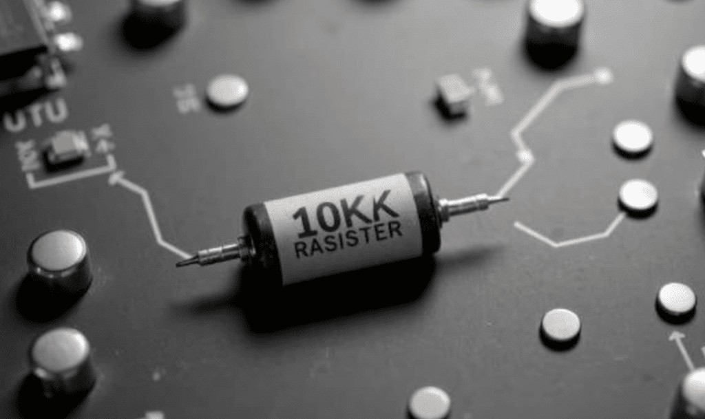
The 10k ohm resistor is one of the most commonly used components in electronic circuits. With a resistance value of 10,000 ohms, it plays critical roles in countless applications, such as voltage division, current limiting, and signal conditioning.
The popularity of the 10k ohm resistor stems from its versatility, wide availability, and suitability for numerous analog and digital circuits. Whether you are working on a simple educational project or a complex industrial system, understanding the characteristics and proper application of 10k ohm resistors is essential for any electronics enthusiast or professional. This guide provides a comprehensive exploration of everything you need to know about these fundamental components, from basic principles to advanced applications.
What is a 10k Ohm Resistor?
A 10kΩ resistor is a small yet vital electronic component that provides 10,000 ohms (Ω) of resistance. It helps control current flow, divide voltages, and protect sensitive components within a circuit. This resistor is widely used in both analog and digital circuits, ensuring stable operation and preventing unexpected electrical faults. The 10kΩ resistor is easily identifiable by its color band code, which allows its resistance value to be determined without a multimeter or other test equipment.
In digital electronics, 10kΩ resistors are frequently used as pull-up or pull-down resistors, helping microcontrollers maintain stable logic states by preventing signals from floating (being undefined). In analog circuits, they play a key role in transistor biasing, ensuring amplifiers function correctly. When combined with capacitors, they form RC networks used to create time delays or provide filtering for oscillator circuits and signal processing. Due to their versatility, 10kΩ resistors are found in everything from simple timers to complex digital interfaces.
Let’s set the jargon aside—a 10k resistor is essentially the “traffic cop” of an electronic circuit. It controls the amount of current flowing through the circuit. “10k” stands for 10,000 ohms, the unit we use to measure electrical resistance. You can think of it as a narrow pipe in a plumbing system—the narrower the pipe, the less water flows through.
These small components are ubiquitous because they strike an optimal balance between not drawing too much current and providing sufficient signal strength.
These resistors work by impeding the flow of current in a circuit, following Ohm’s Law (V = I × R), which states that the voltage (V) across a resistor is proportional to the current (I) flowing through it, with the resistance value (R) being the constant of proportionality.
10k resistors are manufactured using various technologies, each with specific characteristics.
Here is a breakdown of the internal construction of different resistor types:
| Manufacturing Technology | Construction | Typical Applications | Advantages |
|---|---|---|---|
| Carbon Film | Carbon layer deposited on a ceramic substrate | General-purpose circuits, educational projects | Low cost, readily available |
| Metal Film | Thin film of metal alloy on a ceramic base | Precision circuits, measurement equipment | Better tolerance, lower noise |
| Thick Film | Ceramic substrate with resistive paste | Power applications, industrial controls | Higher power handling capability |
| Wirewound | Resistance wire wound around a core | High-power applications, current sensing | Highest power rating, stability |
The fundamental purpose of any 10k ohm resistor is to control current, divide voltage, and set time constants in conjunction with capacitors. The 10k ohm value has become a standard in many circuit designs because it provides a good balance between current consumption and signal strength within typical operating voltage ranges (5-12V).
Types of 10k Resistors and Their Characteristics
Not all 10k ohm resistors are created equal. They come in various package sizes and technologies, each suited for specific applications and environments. Depending on the circuit you are building, you need to select the appropriate type.
Through-hole resistors are the classic components with leads at both ends, ideal for breadboards and hand soldering. Surface-mount device (SMD) resistors are small rectangular components that sit on top of printed circuit boards and are found in virtually all modern electronics.
The main types of 10k resistors include:
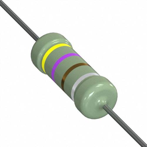
- Through-Hole Resistors: Traditional components for PCB mounting with axial or radial leads.
- Surface Mount Device (SMD) Resistors: Compact components for automated assembly.
- Power Resistors: Designed to handle higher power levels (1W to 25W).
- Precision Resistors: Offer very high accuracy (±0.01% or better) and low Temperature Coefficient of Resistance (TCR).
- Resistor Networks: Multiple resistors in a single package (e.g., SIP/DIP packages).
Different resistor technologies have different performance characteristics:
| Resistor Type | Power Rating Range | Available Tolerances | Temperature Coefficient | Key Features |
|---|---|---|---|---|
| Carbon Composition | 0.125W – 2W | ±5% – ±20% | High (±1000 ppm/°C) | Good pulse handling, legacy technology |
| Carbon Film | 0.125W – 5W | ±1% – ±10% | Medium (±500 ppm/°C) | Inexpensive, readily available |
| Metal Film | 0.125W – 3W | ±0.1% – ±2% | Low (±25 ppm/°C) | Low noise, high stability |
| Metal Oxide Film | 0.5W – 10W | ±1% – ±5% | Medium (±300 ppm/°C) | Good high-temperature performance |
| Thick Film | 0.125W – 25W | ±1% – ±10% | Variable (±100 ppm/°C) | Cost-effective, wide range of packages |
| Wirewound | 3W – 100W | ±1% – ±10% | Low (±75 ppm/°C) | High power, high precision |
| Foil Resistor | 0.5W – 5W | ±0.005% | Very Low (±2 ppm/°C) | Highest precision, best stability |
For some specialized applications, 10k ohm resistors may have unique characteristics. High-temperature resistors can operate at up to 180°C or higher, while high-voltage resistors can withstand hundreds of volts. Current sense resistors typically have very low resistance values, but 10k ohm values can sometimes be used for monitoring circuits.
10k Resistor Color Code Explanation
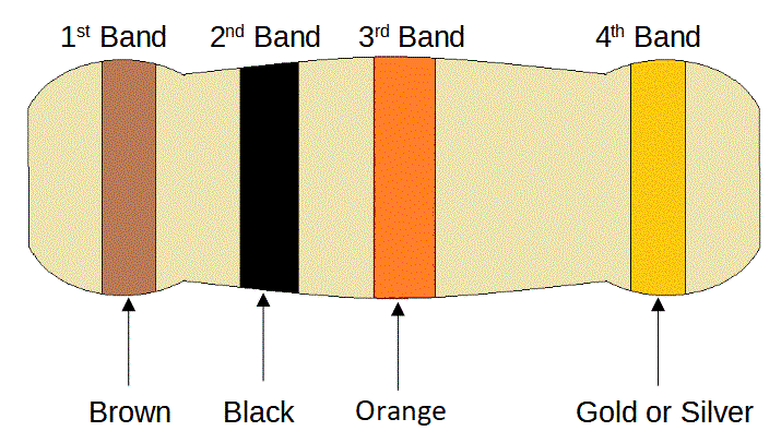
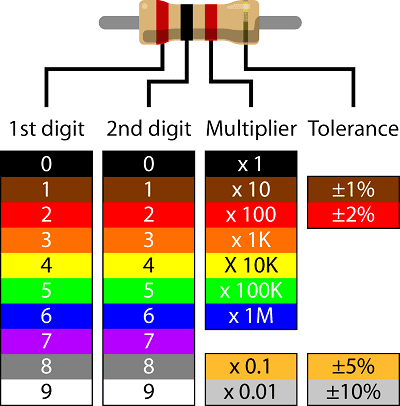
To allow for quick and accurate identification, resistors use a color band marking system. A standard four-band 10kΩ (10,000 ohm) resistor follows a specific color code to denote its resistance value. The first band is brown, representing the first digit, 1. The second band is black, representing the second digit, 0. These two digits combine to make 10. The third band is orange, which serves as the multiplier, indicating that the base number (10) must be multiplied by 1,000, resulting in a total resistance of 10,000 ohms (10kΩ). Finally, the fourth band, gold in this case, indicates the resistor’s tolerance, which is the range of deviation of the actual resistance value from the nominal value. Gold signifies a tolerance of ±5%, meaning the actual resistance could be anywhere between 9,500Ω and 10,500Ω. This tolerance level ensures the resistor remains within an acceptable range for most general-purpose electronic applications, even with minor manufacturing variations.
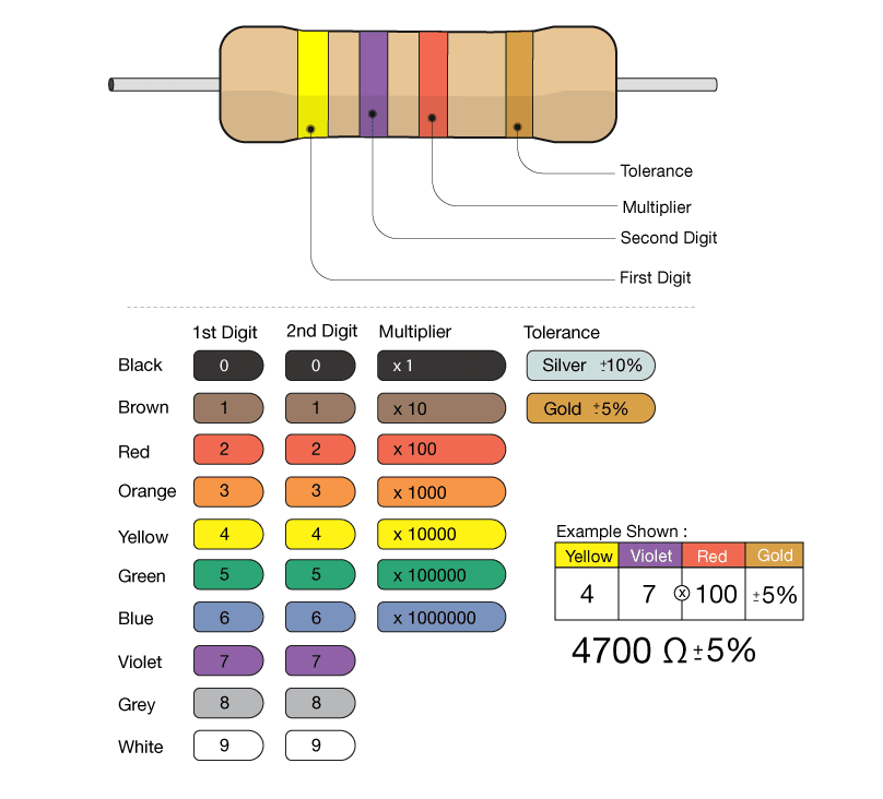
The resistor color coding system might seem complex at first glance, but it can be decoded efficiently and accurately by following a systematic approach. To read the value correctly, start by identifying the orientation of the bands. The end of the resistor where the first band is located is usually closer to the edge than the others; this is your starting point for reading. The last band (often spaced slightly further apart) represents the tolerance and is typically gold or silver. Once orientation is determined, the next step is to identify the digit bands, which determine the base value. The base value is typically found in the first two or three bands, depending on whether the resistor has four, five, or six bands. After establishing the base value, the next band acts as the multiplier, scaling the base value by tens, hundreds, thousands, or even higher. This step is critical, as misinterpreting the multiplier can lead to significant errors in the determined resistance value, affecting circuit performance.
Finally, after calculating the resistance value from the color bands, it is good practice to verify it, especially in applications requiring high precision. You can use a multimeter to measure the actual resistance and confirm it matches the expected value. This step is particularly important for older resistors where the colors may have faded or are difficult to distinguish. For six-band resistors, there is an additional band representing the temperature coefficient, which indicates how much the resistance value changes with temperature. This characteristic is useful for circuits requiring thermal stability, such as precision measurement instruments and high-performance electronic systems.
Technical Specifications and Parameters of 10k Resistors
When selecting or purchasing a 10k resistor, you must consider a range of technical parameters beyond just the resistance value. Here is a detailed explanation of the key specifications:
1. Resistance Value
- Nominal Value: 10kΩ (10,000 Ohms).
- Tolerance: The allowable deviation range of the actual resistance from the nominal value. Common values include:
- ±1%: For precision applications like measurement circuits and voltage dividers. The actual resistance lies between 9.9kΩ and 10.1kΩ.
- ±5%: For general applications like pull-up/pull-down resistors and LED current limiting. The actual resistance lies between 9.5kΩ and 10.5kΩ.
2. Rated Power
The maximum power the resistor can continuously dissipate safely. Exceeding this value will cause the resistor to overheat and potentially burn out. Common ratings are:
- Through-Hole: 1/8W (0.125W), 1/4W (0.25W), 1/2W (0.5W), etc.
- Surface-Mount: Varies by size; e.g., 0402 is typically 1/16W (0.063W), 0805 is 1/8W (0.125W), etc.
Power Calculation Formula: ( P = I² × R ) or ( P = V² / R ). For example, a 1/4W 10k resistor has a maximum safe operating voltage of ( V = \sqrt{P × R} = \sqrt{0.25 × 10000} = 50V ).
3. Temperature Coefficient
Indicates how much the resistance value changes with temperature, measured in ppm/°C (parts per million per degree Celsius).
- Meaning: For example, a 10k resistor with a 100 ppm/°C coefficient will change its resistance by ( 10000Ω × (100 / 1,000,000) = 1Ω ) for every 1°C change in temperature.
- Common Values:
- Thick Film: Typically ±100 ppm/°C to ±200 ppm/°C.
- Metal Film: Superior, can reach ±50 ppm/°C or better.
- For high-precision, high-stability applications (e.g., precision instruments), low-temperature coefficient resistors are required.
4. Package Type
- Through-Hole:
- Axial: Leads extend from each end of the resistor body. Common in older or higher-power circuits.
- Radial: Leads extend from the same side of the body.
- Surface-Mount:
- Named by size: 0201, 0402, 0603, 0805, 1206, etc. Larger numbers generally indicate higher power capacity.
5. Other Parameters
- Operating Temperature Range: The ambient temperature range within which the resistor can function normally.
- Maximum Working Voltage: The highest voltage that can be safely applied across the resistor terminals.
- Noise: The inherent electrical noise generated by the resistor itself, which must be considered in high-sensitivity circuits like amplifiers.
Applications of 10k Resistors in Electronic Circuits
The 10k resistor is a “jack-of-all-trades” in the electronics world, with extremely wide-ranging applications. Here are some typical use cases:
1. Pull-Up and Pull-Down Resistors
This is one of the most common applications in digital circuits.
- Pull-Up Resistor: Connects an uncertain signal (like a microcontroller’s input pin) to a high logic level (Vcc) via a 10k resistor, ensuring the pin remains in a defined logic ‘1’ state when not being actively driven low. Common in I²C buses and button detection (where the button connects the pin to ground).
- Pull-Down Resistor: The opposite of pull-up; connects the pin to a low logic level (GND) via a resistor, ensuring a default logic ‘0’ state.
2. Voltage Divider
Two resistors in series can derive a lower voltage from a higher voltage. A 10k resistor is often used as one of them.
- Formula: ( V_{out} = V_{in} × \frac{R2}{R1 + R2} )
- Applications:
- Level Shifting: Converting a 5V signal to a 3.3V signal.
- Sensor Interfacing: Many analog sensors (like thermistors, photoresistors/LDRs) work by changing their resistance based on the environment. They are used in a voltage divider configuration with a fixed 10k resistor, and the voltage at the divider’s midpoint is measured to sense the environmental change.
3. Current Limiting Resistor
Used to restrict the current flowing through sensitive components (like LEDs) to prevent damage.
- For LEDs: While a 10k resistor is generally too large for a standard LED (resulting in a very dim glow), it can still be used for low-current indicators or when working with higher voltages. The formula for calculating the current-limiting resistor is: ( R = \frac{V_{source} – V_{LED}}{I_{LED}} ).
4. Operational Amplifier Circuits
- Inverting/Non-Inverting Amplifiers: 10k resistors are commonly used in the feedback network or as input resistors to set the amplifier’s gain.
- Voltage Followers: Although they might not seem to use resistors directly, small series resistors (e.g., 10Ω) at the input/output can be used to isolate capacitive loads and improve stability.
5. RC Timing Circuits
A resistor and capacitor in series can form a simple delay or oscillator circuit.
- Time Constant: ( τ = R × C ). The time constant for a 10k resistor and a 10µF capacitor is ( 0.1s ).
- Applications: Switch debouncing, power-on reset circuits, tunable oscillators (e.g., with a 555 timer).
6. Filters
Combined with a capacitor, they can form passive filters.
- Low-Pass Filter: The resistor is in series with the signal path, and the capacitor is in parallel to ground. The cutoff frequency is ( f_c = \frac{1}{2πRC} ). A 10k resistor and a 1nF capacitor yield a cutoff frequency of approximately 15.9kHz.
- High-Pass Filter: The capacitor is in series with the signal path, and the resistor is in parallel to ground.
Summary
| Parameter/Application | Description/Example |
|---|---|
| Core Parameters | Resistance (10kΩ), Tolerance (±1%, ±5%), Rated Power (1/4W, etc.), Temp. Coefficient, Package |
| Pull-Up/Pull-Down | Ensures digital pins are in a defined logic state |
| Voltage Divider | Used for level shifting, sensor reading (e.g., with a thermistor) |
| Current Limiting | Protects components like LEDs (calculate based on actual current needs) |
| RC Circuits | Forms timers, oscillators, filters |
| Op-Amp Circuits | Sets amplifier gain |
When selecting a 10k resistor, it is crucial to weigh these parameters according to your specific application (precision, power, environment) to ensure circuit reliability and performance.
Troubleshooting Common 10k Resistor Issues
While resistors are generally reliable components, various problems can arise when using 10k ohm resistors in electronic circuits. Understanding these potential issues and how to diagnose them is crucial for effective troubleshooting.
Common Problems with 10k Resistors:
- Incorrect Resistance Value:
- Manufacturing defects (rare from reputable suppliers)
- Permanent value shift due to overheating
- Physical damage from mechanical stress
- Overheating and Damage:
- Exceeding the power rating
- Insufficient heat dissipation
- High ambient temperature without proper derating
- Intermittent Connections:
- Poor solder joints
- Lead damage or corrosion
- Internal connection issues (especially in wirewound types)
- Noise Issues:
- Particularly high noise in carbon composition resistors.
- Insufficient filtering in sensitive circuits
- Frequency-Related Problems:
- Parasitic effects in high-frequency applications
- Wirewound resistors acting as inductors
Resistor-Related Circuit Troubleshooting Guide:
| Symptom | Possible Causes | Testing Method | Solutions |
|---|---|---|---|
| Circuit not working | Resistor open, wrong value installed. | Visual inspection, resistance measurement | Replace resistor, verify value. |
| Overheating component | Resistor overloaded, wrong value. | Temperature measurement, power calculation | Use higher power rating resistor, improve ventilation. |
| Inaccurate readings | Resistor out of tolerance, temperature effects. | Precision resistance measurement | Use higher tolerance resistor, control temperature. |
| Intermittent operation | Poor connection, cracked resistor. | Visual inspection, tap test | Re-solder or replace resistor. |
| Noisy signal | High-noise resistor type, poor filtering. | Oscilloscope observation | Use metal film resistor, add filtering. |
| Frequency-dependent behavior | Parasitic inductance/capacitance | Frequency response analysis | Choose frequency-appropriate resistor type. |
When measuring the value of a 10k ohm resistor during troubleshooting:
- For an accurate measurement, ensure at least one end of the resistor is disconnected from the circuit.
- Be aware that some digital multimeters may not measure high-value resistors accurately.
- Consider the effect of body resistance when holding the resistor leads.
- For precise measurements, use the four-wire (Kelvin) measurement technique.
Prevention is often the best approach to resolver resistor-related issues:
- Always calculate power dissipation and apply appropriate derating.
- Select the correct resistor type for the application.
- Use proper soldering techniques to avoid mechanical stress.
- Consider environmental factors like temperature and humidity.
- Implement over-voltage or over-current protection circuits.
Pro Tip: It’s always best to keep a stock of different types of 10k ohm resistors. You never know when you’ll need to swap one out during troubleshooting. Bettlink offers a wide variety of resistors, giving you the flexibility to choose the exact type you need.
Conclusion
The 10kΩ resistor is a fundamental yet crucial component in electronic circuits, helping them operate smoothly and reliably. Understanding how to identify a 10kΩ resistor via its color bands and mastering its uses can empower you to design better circuits. Whether in a simple project or a complex device, the 10kΩ resistor is key to building and repairing electronics, ensuring circuit stability and precision.


0 Comments