
1 Introduction
In electronic circuit design and application, the resistor stands as one of the most fundamental and core components, playing crucial roles in controlling current and dividing voltage. Among the multitude of resistance values, the 3.3K ohm resistor holds a significant position in the electronics industry due to its unique numerical characteristics. This specific value resistor is widely used in digital circuits, analog circuits, and mixed-signal systems, serving as a key component for interfacing different voltage levels, implementing signal conditioning, and ensuring stable system operation.
The importance of the 3.3K resistor lies primarily in its versatility and practicality. In digital circuits, it is often used as a pull-up or pull-down resistor to ensure signals maintain a defined logic level when not actively driven. In analog circuits, it participates in forming feedback networks for amplifiers and filters, influencing circuit gain and frequency response. In power management, it is used for current limiting, voltage division, and sensing. As electronic devices evolve towards miniaturization, high precision, and high reliability, performance requirements for 3.3K resistors are also increasing, driving advancements in various technologies and package forms. This guide will provide a comprehensive analysis of the technical characteristics, application scenarios, and selection considerations for 3.3K resistors, serving as a professional reference for electronics engineers.
2 What is a Resistor
A resistor is a passive electronic component designed to present a specific opposition to the flow of electric current. It is one of the most basic and commonly used components in electronic circuits. The primary functions of a resistor are to limit current, divide voltage, adjust signal levels, and act as a heating element. Without resistors, most electronic circuits would not function properly, as it would be impossible to control the distribution of current and voltage within the circuit.
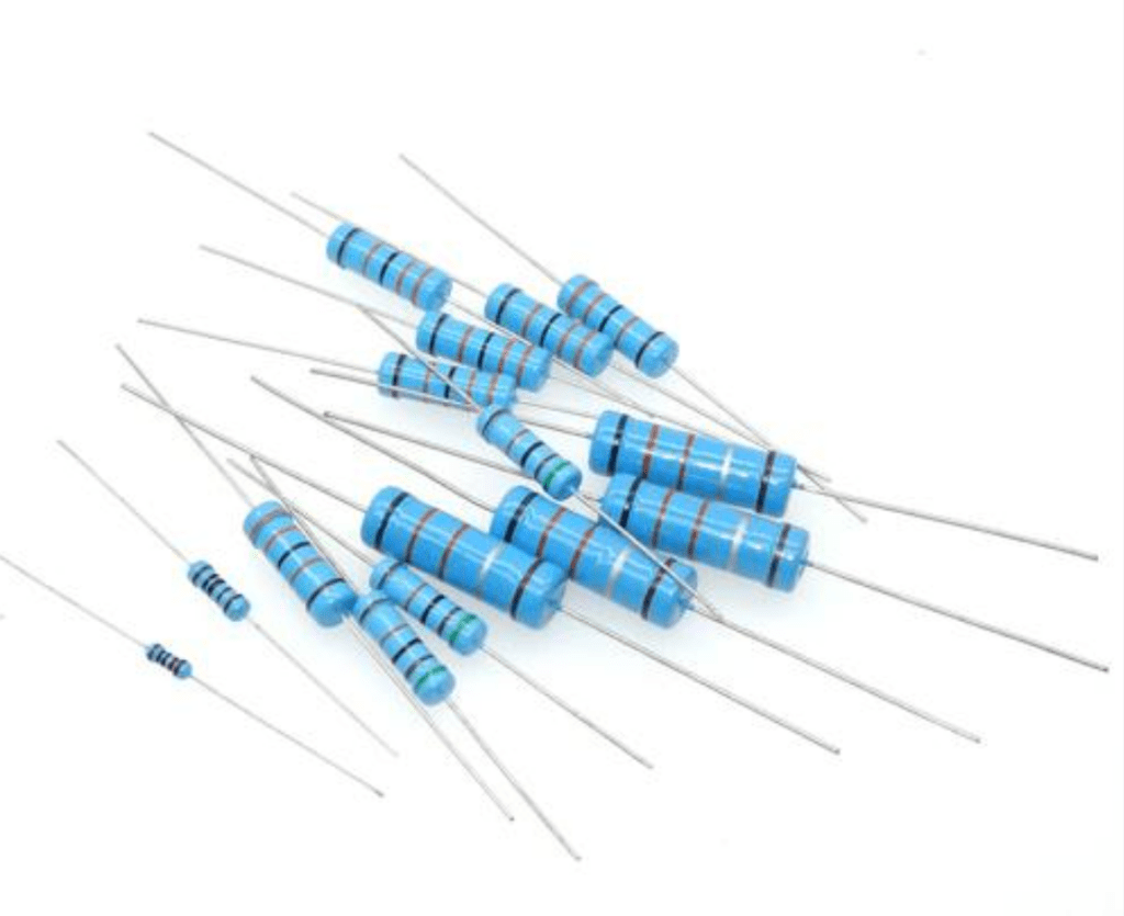
From a structural and operational principle perspective, resistors can be divided into several types, each with its specific application scenarios and performance characteristics. Wirewound resistors consist of a metal resistance wire wound around an insulating core; they can withstand relatively high power but possess significant parasitic inductance and capacitance, making them unsuitable for high-frequency applications. Metal film resistors are made by vacuum depositing a thin layer of metal or metal oxide onto a ceramic substrate, with the resistance value precisely adjusted via laser trimming; they offer high precision, low temperature coefficient, and low noise. Thick film resistors (such as chip resistors) are fabricated by screen printing a metal-glass glaze paste onto a ceramic substrate and then firing it; they are low-cost and small in size, representing the most widely used resistor type today. Metal foil resistors are made by bonding a specific alloy foil to a ceramic substrate and forming the resistor pattern using photolithography; they offer the highest performance but also the highest cost.
The core parameters of a resistor include resistance value, tolerance (accuracy), rated power, temperature coefficient, working voltage, and frequency characteristics. These parameters collectively determine a resistor’s suitability and performance in a specific application. In practical applications, engineers need to consider these parameters comprehensively based on circuit requirements to select the most appropriate resistor type and specification.
3 Basic Parameters of 3.3K Ohm Resistors
The performance of a 3.3K ohm resistor is entirely determined by its parameter specifications. Understanding these parameters is crucial for correct selection and application. Resistance Value is the most fundamental parameter, indicating the magnitude of opposition the resistor presents to current flow; 3.3KΩ denotes a resistance value of 3300 ohms. This specific value offers broad applicability in electronic circuits, particularly in 5V, 3.3V, and 1.8V logic systems, where it provides appropriate current limiting and voltage division.
Tolerance (also known as accuracy) refers to the permissible maximum deviation between the actual resistance value and the marked nominal value, usually expressed as a percentage. For 3.3K resistors, common tolerance grades include ±0.1% (e.g., Vishay HP31K332MCXWPEC), ±1% (e.g., Walsin WR02X3301FAL, Uniohm MFR series), and ±5% (e.g., RS PRO aluminum shell resistor, TT Electronics W21-3K3JI). Resistors with higher precision typically have higher production costs and prices. In general digital circuits, a ±5% tolerance is often sufficient, whereas precision measurement, instrumentation, and similar applications often require high-precision resistors of ±1% or even ±0.1%.
Rated Power refers to the maximum power that a resistor can safely dissipate under continuous long-term operation. Exceeding this value may cause the resistor to overheat and fail. The power rating for 3.3K resistors spans an extremely wide range, from 1/20W (0.05W) for 0201 packages to 300W for large aluminum shell resistors. Common power specifications include 1/20W (0201 package), 1/8W (0805 package), 1/2W (metal film resistor), 3W (wirewound resistor), and 20W (power wirewound resistor). When selecting a power rating, the actual power dissipation of the resistor in the circuit must be considered, with an appropriate safety margin.
Temperature Coefficient (TCR) indicates the relative change in the resistor’s value per degree Celsius change in temperature, expressed in units of ppm/°C. This parameter is crucial for applications requiring stable operation over a wide temperature range. The TCR of 3.3K resistors varies significantly depending on the technology: high-precision metal film resistors can achieve ±5 ppm/°C, standard metal film resistors are around ±50 ppm/°C or ±75 ppm/°C, while thick film chip resistors are typically ±100 ppm/°C or higher.
Table: Comparison of Key Parameters for 3.3K Ohm Resistors
| Parameter Type | Typical Range | Impact on Application | Example Part Number |
|---|---|---|---|
| Tolerance | ±0.1% to ±5% | Affects circuit accuracy and consistency | Vishay HP31K332MCXWPEC (±0.1%) |
| Rated Power | 1/20W to 300W | Determines current carrying capacity | RS PRO Aluminum Shell Resistor (300W) |
| Temperature Coefficient | ±5 ppm/°C to ±500 ppm/°C | Affects temperature stability | Vishay HP31K332MCXWPEC (±5 ppm/°C) |
| Operating Temperature | -55°C to +275°C | Determines environmental suitability | Vishay Dale PWR263S-20-3301F (-55°C to +275°C) |
Other important parameters include Maximum Working Voltage (e.g., 100V for W21-3K3JI, 1000V for PWR263S-20-3301F), Package Form (SMD/Through-Hole), Temperature Range, and Stability (long-term resistance change). In practical applications, it is necessary to consider these parameters comprehensively based on circuit requirements, environmental conditions, and service life expectations to select the most suitable 3.3K resistor.
4 How to Identify a 3.3K Resistor
Correctly identifying a 3.3K resistor is crucial for electronics engineers, technicians, and hobbyists. The identification method depends primarily on the resistor’s type and package form, typically achieved through three methods: visual marking, color coding, and measurement verification.
For Chip Resistors (SMD), due to their tiny size, a numerical coding system is usually used for identification. The identification of a 3.3K chip resistor mainly follows two methods: the three-digit code and the four-digit code. In the three-digit code, the first two digits represent significant figures, and the third digit represents the multiplier (power of 10). Therefore, 3.3KΩ is marked as “332”, meaning 33 × 10² = 3300Ω = 3.3KΩ. The four-digit code is used for higher precision resistors; the first three digits represent significant figures, and the fourth digit is the multiplier. Thus, 3.3KΩ would be marked as “3301”, meaning 330 × 10¹ = 3300Ω. Some miniature chip resistors (like the 01005 package) may have no marking at all due to space constraints and must be identified via their packaging label.
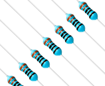
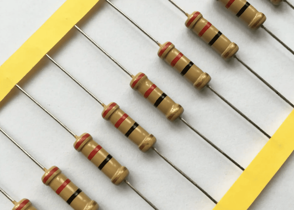
For Through-Hole Resistors, the traditional color band coding system is still widely used. 3.3KΩ resistors typically come in either four-band or five-band forms. The color bands for a 3.3KΩ resistor in the four-band system are: Orange(3)-Orange(3)-Red(×100)-Gold(±5%). The five-band system is used for higher precision resistors; the colors are: Orange(3)-Orange(3)-Black(0)-Brown(×10)-Brown(±1%). Precision metal film resistors like the Vishay HP31K332MCXWPEC (±0.1%) might use a more complex coding system, potentially including an additional temperature coefficient band.
Power Resistors and Special Purpose Resistors often have numerical values printed directly on them due to their larger size. For example, the RS PRO 300W aluminum shell resistor is directly marked with “3.3KΩ”, “300W”, and “±5%”. The Vishay Dale PWR263S-20-3301F power wirewound resistor also clearly displays all key specifications on its casing.
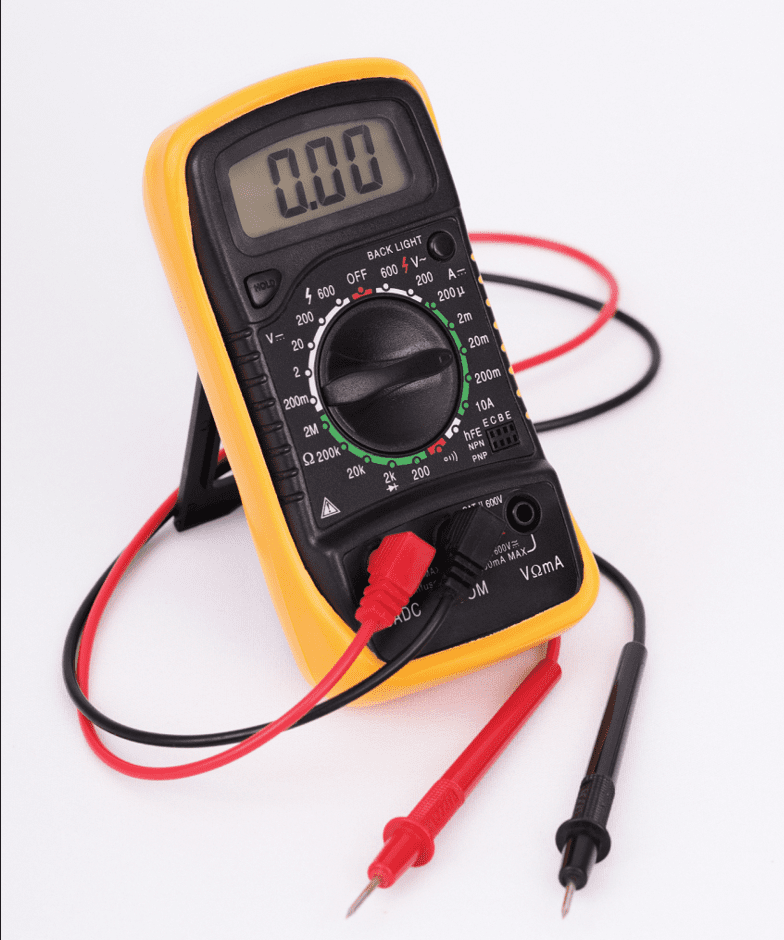
In practical work, when markings are unclear or identification is doubtful, using a Digital Multimeter (DMM) to measure the resistance value is the most reliable verification method. Select the ohmmeter function, connect the test leads to both ends of the resistor (polarity does not matter), and read the value directly. It is important to note that in-circuit measurement might be affected by parallel components in the circuit; the most accurate method is to desolder one lead of the resistor before measuring.
5 Functions of the 3.3K Resistor
The 3.3K resistor serves diverse and critical roles in electronic circuits, with its specific function depending on its position and configuration within the circuit. Understanding these functions helps engineers apply this resistance value correctly in their designs.
Current Limiting is one of the most basic functions of the 3.3K resistor. In LED indicator circuits, a 3.3K resistor connected in series with an LED limits the current flowing through the LED, preventing damage due to excessive current. For example, with a 5V supply, a 3.3K resistor can limit the LED current to approximately 1mA (considering an LED forward voltage drop of about 1.7V), making it suitable for use as a power indicator light. At the input/output pins of transistors or integrated circuits, the 3.3K resistor is also commonly used to limit input current or output load current, protecting semiconductor devices from accidental overcurrent damage.
Voltage Division is another important application. A 3.3K resistor combined with other resistors forms a voltage divider network, converting a high voltage into a lower, measurable voltage signal. In sensor interface circuits, a 3.3K resistor can form a voltage divider with variable resistive elements like photoresistors or thermistors, converting resistance changes into voltage changes for processing by subsequent circuits. In power monitoring circuits, a voltage divider network involving a 3.3K resistor can proportionally reduce a high voltage (e.g., 12V, 24V) to within the input range (e.g., 3.3V) of an ADC (Analog-to-Digital Converter), enabling voltage monitoring.
Pull-up/Pull-down Resistor applications are typical uses for the 3.3K resistor in digital circuits. In open-collector (OC) or open-drain (OD) output structures, a 3.3K pull-up resistor ensures the output can provide a defined high voltage level. In serial buses like I²C, a 3.3K resistor can serve as a pull-up resistor, pulling the bus level high when released, while also limiting the charging current for the bus capacitance, affecting communication speed and power consumption. On microcontroller input pins, a 3.3K pull-down resistor can prevent logic errors caused by noise when the pin is floating.
Signal Conditioning is an important function of the 3.3K resistor in analog circuits. In operational amplifier circuits, the 3.3K resistor, in conjunction with other resistors, can set the amplifier’s gain. In RC filter networks, a 3.3K resistor combined with a capacitor can form low-pass, high-pass, or band-pass filters, controlling the circuit’s frequency response. In oscillator circuits, a 3.3K resistor can determine the oscillation frequency in combination with a capacitor, or limit the input current of a comparator.
Impedance Matching is a key application in high-frequency circuits. A 3.3K resistor can be used for transmission line termination matching to reduce signal reflection and maintain signal integrity. Although RF systems typically use standard impedances of 50Ω or 75Ω, in some specific applications, a 3.3K resistor can be used as a termination resistor or damping resistor.
6 Advantages and Disadvantages of the 3.3K Resistor
As a commonly used component in electronic design, the 3.3K resistor possesses a series of notable advantages, while also having certain limitations. Understanding these characteristics is crucial for optimizing circuit design.
Advantages
Versatility and Availability are among the most prominent advantages of the 3.3K resistor. This resistance value is readily available in large quantities from the vast majority of electronic component suppliers, covering various technology types, accuracy grades, and power specifications. Designers can easily find a 3.3K resistor suitable for their specific application, with a rich selection ranging from low-cost consumer-grade products to high-reliability industrial-grade components.
Circuit Design Optimization is another significant advantage of the 3.3K resistor. In 5V digital systems, when used as a pull-up resistor, it provides sufficient drive capability while maintaining low power consumption. In 3.3V systems, its value matches the input impedance of common integrated circuits, effectively reducing load effects. Its resistance value generally strikes a good balance between signal quality and power consumption in most applications.
Compatibility with Standard Logic Levels makes the 3.3K resistor an ideal choice for digital system design. In TTL and CMOS logic level interfaces, the 3.3K resistor can provide appropriate source and sink currents without generating excessive power dissipation. In applications like the I²C bus, 3.3K is a commonly used pull-up resistor value, balancing bus capacitance and communication speed.
In terms of Precision and Stability, modern manufacturing processes enable 3.3K resistors to achieve high accuracy and stability. Metal film technology can achieve tolerances of ±0.1% or even higher, with temperature coefficients as low as ±5 ppm/°C and excellent long-term stability, making them suitable for precision applications.
Disadvantages
Power Dissipation Considerations are a limitation of the 3.3K resistor in specific applications. In high-voltage applications, such as when used directly across a rectified mains voltage of 300V DC, the power dissipation across a 3.3K resistor would exceed 0.5W significantly (P=V²/R=300²/3300≈27W), necessitating the selection of a high-power resistor, which increases cost and space requirements.
High-Frequency Performance Limitations are mainly evident in parasitic parameters. The parasitic inductance and capacitance of wirewound resistors make them unsuitable for high-frequency applications. Even for chip resistors, when operating frequencies enter the GHz range, parasitic capacitance and inductance cause the resistor’s behavior to deviate from ideal characteristics.
Balancing Accuracy and Cost is another factor to consider during design. Although high-precision 3.3K resistors (e.g., ±0.1%) offer excellent performance, their cost can be several times or even tens of times higher than standard tolerance (±5%) products. This can be a limiting factor in cost-sensitive applications.
Size and Power Limitations exist in miniaturization applications. A 3.3K resistor in a 0201 package has a power rating of only 1/20W (0.05W), which might be insufficient in small devices requiring a certain power handling capability. Conversely, high-power resistors (like a 300W aluminum shell resistor) are bulky (141.4×72.5×41.8mm) and difficult to use in space-constrained applications.
7 Comparison of 3.3K and 2.2K Resistors
In electronic circuit design, both 3.3K and 2.2K are common resistance values. Understanding their differences and suitable application scenarios is crucial for optimizing design. Each resistance value has its own characteristics, suited for different application requirements.
From the perspective of Basic Parameters, the most obvious difference is the resistance value. The resistance of a 3.3K resistor is 50% higher than that of a 2.2K resistor. This means that under the same voltage, the current through a 3.3K resistor is about 33% smaller than through a 2.2K resistor. For example, at 5V, the current through a 3.3K resistor is about 1.52mA, while through a 2.2K resistor it is about 2.27mA. This difference directly affects their behavior and application in circuits.
In Voltage Divider Circuits, using different resistance values affects the sensitivity of the division ratio and power dissipation. For the same pull-up resistor value, a 3.3K pull-down resistor provides a more “robust” logic low level compared to a 2.2K resistor, but the rise time might be longer. In voltage reference circuits, a 3.3K resistor can provide higher input impedance, reducing the impact on the preceding stage circuit, but may increase susceptibility to noise.
In Current Limiting applications, the choice between a 3.3K or a 2.2K resistor depends on the required current magnitude and power dissipation considerations. In LED circuits, a 3.3K resistor provides less current, resulting in lower LED brightness but lower power consumption; a 2.2K resistor provides more current, resulting in higher brightness but increased power dissipation. In transistor base drive circuits, a 3.3K resistor provides a smaller base current, which might affect switching speed, but reduces the burden on the drive circuit.
From a Frequency Response perspective, in RC filter networks, the cutoff frequency formed by a 3.3K resistor combined with a specific capacitor is lower than that formed using a 2.2K resistor. For example, the cutoff frequency of a low-pass filter formed by a 3.3K resistor and a 100nF capacitor is approximately 482Hz, whereas the same capacitor combined with a 2.2K resistor yields a cutoff frequency of about 723Hz. This makes the 3.3K resistor more suitable for applications requiring a lower cutoff frequency.
Table: Comparison of Application Characteristics of 3.3K vs. 2.2K Resistors
| Application Scenario | 3.3K Resistor Characteristics | 2.2K Resistor Characteristics | Preferred Condition |
|---|---|---|---|
| LED Indicator (5V Supply) | Current ~1mA, Low Power | Current ~1.5mA, High Brightness | Choose based on brightness/power requirement |
| Pull-up Resistor (I²C Bus) | Longer Rise Time, Lower Power | Shorter Rise Time, Higher Power | Choose lower value for large bus capacitance |
| RC Low-Pass Filter (100nF) | Cutoff Freq. ~482Hz | Cutoff Freq. ~723Hz | Choose based on target frequency |
| 5V to 3.3V Voltage Divider | Higher Input Impedance, Lighter Load on Prior Stage | Lower Input Impedance, Better Noise Immunity | Choose based on prior stage drive capability |
Regarding Power Dissipation and Heating, under the same voltage, the power dissipation of a 3.3K resistor is about 67% of that of a 2.2K resistor, with correspondingly lower heat generation. In high-voltage or high ambient temperature applications, this can be the decisive factor for choosing a 3.3K resistor.
In Digital Logic Interfaces, both 3.3K and 2.2K resistors can be used for level shifting and signal conditioning, but with different effects. The 3.3K resistor offers lower power consumption while providing sufficient pull-up current, whereas the 2.2K resistor can provide stronger drive capability, suitable for situations with heavier loads.
8 Summary
The 3.3K resistor, as a ubiquitous component in electronic circuits, is important not only for its specific resistance value but also for the versatility and reliability it demonstrates across various circuit environments. From simple current limiting to complex signal conditioning, from low-power digital circuits to high-power industrial applications, the 3.3K resistor finds its purpose. This specific resistance value has established a solid position in the electronics industry, becoming a key element for connecting different electronic components and ensuring stable system operation.
With the continuous development of electronic technology, the 3.3K resistor is also constantly evolving. Technological progress has brought about smaller sizes, higher precision, better stability, and superior high-frequency characteristics. Thin-film technology enables 3.3K resistors to achieve ±0.1% tolerance and ±5 ppm/°C temperature coefficients, while new materials and packaging technologies improve power density and environmental suitability. The trend towards integration has also impacted the resistor field, with resistor networks and SiP (System-in-Package) often including 3.3K resistance values. Looking forward, the 3.3K resistor will continue to play a vital role in the electronics industry, especially in emerging fields like new energy vehicles, 5G communications, the Internet of Things (IoT), and industrial automation, where demand for high-performance 3.3K resistors will continue to grow. Simultaneously, the trend towards localization and substitution will bring more choices to the market, potentially driving cost optimization and technological innovation.
When selecting and using 3.3K resistors, electronics engineers need to comprehensively consider multiple requirements, including resistance tolerance, power rating, temperature characteristics, package form, cost factors, and application environment. The correct choice not only ensures the realization of circuit functions but also enhances system reliability and service life. Whether choosing a standard thick-film resistor or a high-precision metal-film resistor, understanding the characteristics and application principles of the 3.3K resistor is the foundation for making optimal design decisions.


0 Comments