
Introduction
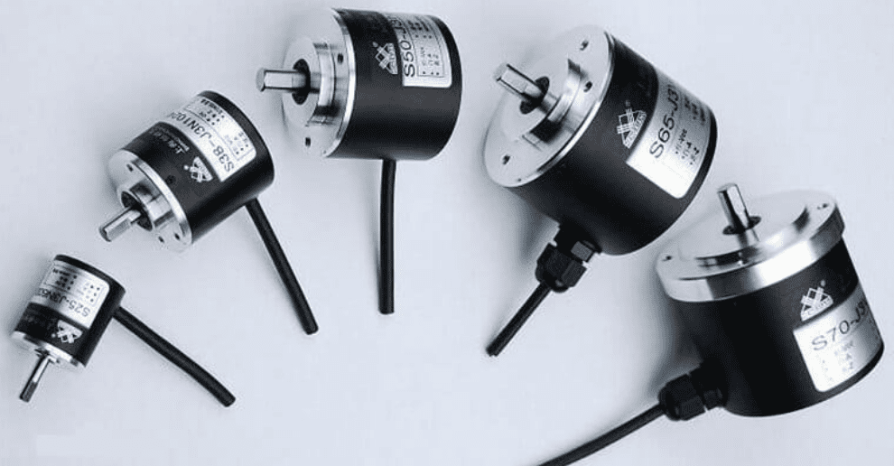
If you search for the definition of an encoder, you may encounter a wide and confusing array of responses. In our application context, encoders are devices used for mechanical motion control. Encoders can be found in machinery across all industries. You’ll discover encoders being used in cut-to-length applications, plotters, robotics, packaging, conveying, automation, sorting, filling, imaging, and many more fields.
You may have never noticed them, but they are indeed present. In this technical manual, we will provide you with fundamental knowledge about what an encoder is and its functions.
What is an Encoder?
Simply put, an encoder is a sensing device that provides feedback. It is a device capable of compiling signals (such as bitstreams) or data and converting them into signal forms that can be used for communication, transmission, and storage. The encoder converts motion into an electrical signal that can be read by some type of control device in a motion control system, such as a counter or PLC. The feedback signal sent by the encoder can be used to determine position, count, speed, or direction. A control device can use this information to send commands for specific functions.
Application Examples:
- Cut-to-Length Applications: An encoder with a measuring wheel informs the control device how much material has been fed, enabling the control device to know when to cut.
- Observatories: Encoders provide positional feedback to actuators, indicating the position of a movable mirror.
- Railcar Lifting Jacks: Encoders provide precision motion feedback, ensuring the jacks lift in unison.
- Precision Servo Labeling Systems: The PLC uses the encoder signal to control the timing and speed of bottle rotation.
- Printing Applications: Feedback from the encoder activates a print head to create a mark at a specific location.
- Large Cranes: Encoders mounted on motor shafts provide positional feedback, allowing the crane to know when to pick up or release its load.
- Bottle/Jar Filling Lines: Feedback informs the filling machines of the container positions.
- Elevators: Encoders tell the controller when the car has reached the correct floor and is properly aligned. Encoder motion feedback ensures elevator doors open level with the floor. Without encoders, you might find yourself climbing in or out of an elevator car.
- Automated Assembly Lines: Encoders provide motion feedback to robots. On an automotive assembly line, this ensures robotic welding arms have the correct information to weld in the right locations.
In any application, the process is the same: the encoder generates a count and sends it to the controller, which then sends a signal to the machine to perform a specific function.
How Does an Encoder Work?
Encoders use different types of technologies to generate signals, including mechanical, magnetic, resistive, and optical – with optical being the most common. In optical sensing, the encoder provides feedback based on the interruption of light.
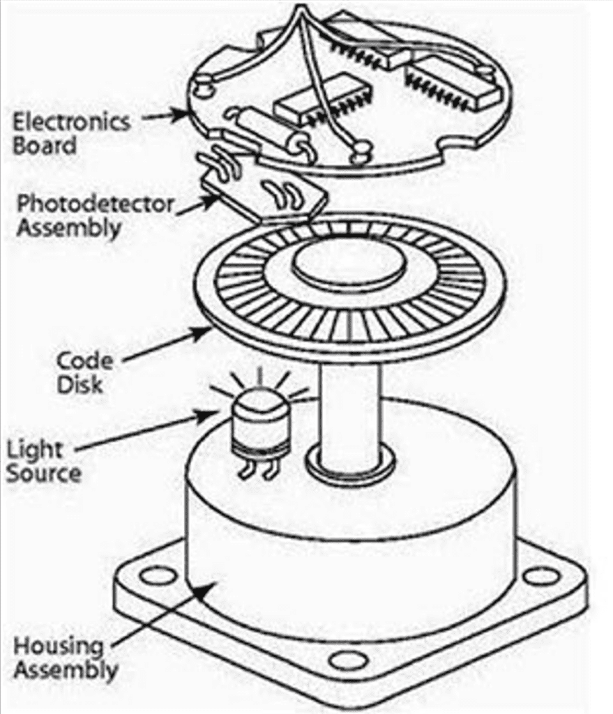
The diagram above outlines the basic construction of an incremental rotary encoder using optical technology. A beam of light emitted from an LED passes through a code disk, which is patterned with opaque lines (similar to bicycle spokes). As the encoder shaft rotates, the light beam from the LED is interrupted by the opaque lines on the code disk before being detected by the photodetector assembly.
This generates a pulse signal: light = ON; no light = OFF. This signal is sent to the counter or controller, which then issues a signal to perform the desired function.
Classification of Encoders
Based on the detection principle, encoders can be classified into optical, magnetic, inductive, and capacitive types. According to their scaling method and signal output form, they can be divided into three types: incremental, absolute, and hybrid.
- Incremental Encoder
Incremental encoders directly utilize the photoelectric conversion principle to output three sets of square wave pulses: A, B, and Z. The phase difference between the A and B pulses is 90 degrees, allowing for easy determination of the rotation direction. The Z pulse outputs one pulse per revolution, used for reference point positioning. Their advantages include simple structure, typical mechanical life exceeding tens of thousands of hours, strong anti-interference capability, high reliability, and suitability for long-distance transmission. The disadvantage is the inability to output the absolute positional information of the shaft. - Absolute Encoder
An absolute encoder is a sensor that directly outputs digital values. On its circular code disk, there are several concentric code tracks along the radial direction. Each track consists of transparent and opaque sectors. The number of sectors on adjacent code tracks is a power of two. The number of code tracks on the disk determines its binary bit count. One side of the disk has a light source, and the other side has a photosensitive element corresponding to each code track. As the disk rotates to different positions, each photosensitive element converts the received light (or lack thereof) into corresponding level signals, forming a binary number. The characteristic of this encoder is that it does not require a counter and can read a fixed digital code corresponding to the position at any shaft angle. Clearly, there must be N code tracks. - Hybrid Absolute Encoder
Hybrid absolute encoders output two sets of information: one set is used to detect the magnetic pole position, providing absolute information; the other set is identical to the output information of an incremental encoder.
The following sections detail several common types of encoders.
Applications of Photoelectric Encoders
- Angle Measurement: Used in car driving simulators as sensors for measuring steering wheel rotation angle. Used in gravimeters by connecting its shaft to the compensation knob shaft. Used in torsion meters to measure torsional angle changes, e.g., in torsion testing machines, fishing rod performance tests. Used in pendulum impact testers to calculate the impact swing angle.
- Length Measurement: Length counters use the circumference of a roller to measure object length and distance. Cable extension transducers use the circumference of a winding wheel to measure object length. Direct coupling measurement, coupling with the main shaft of a drive mechanism for linear displacement, measuring via the number of output pulses. In medium detection, linear displacement information is transmitted via racks, sprockets on rotating chains, and timing belt pulleys.
- Speed Measurement: Linear Speed: Measured by connecting to a length counter, determining production line speed. Angular Speed: Measuring the speed of motors, shafts, etc., using encoders.
- Position Measurement: In machine tools, used to memorize coordinate positions of various axes, e.g., in drilling machines. In automation, used to control specific actions at defined positions, such as in elevators and hoists.
- Synchronous Control: Controlling transmission elements synchronously via angular or linear velocity to achieve tension control.
Incremental Encoder (Rotary Type)
- Working Principle
The core of an incremental encoder contains a shaft-mounted photoelectric code disk with concentric circular, alternating transparent and opaque lines. These lines are read by a photoelectric transmitter and receiver, producing four sets of sinusoidal wave signals combined into A, B, C, D. Each sine wave has a 90-degree phase shift (relative to a 360-degree cycle). The C and D signals are inverted and superimposed on the A and B phases to enhance signal stability. Additionally, a Z-phase pulse is output once per revolution, representing the zero reference position.
Because the A and B phases are 90 degrees apart, comparing which phase leads (A or B) determines the encoder’s rotation direction. The encoder’s zero reference position can be obtained via the Z pulse.
Encoder code disk materials include glass, metal, and plastic. Glass disks have very thin lines deposited on glass, offering good thermal stability and high accuracy. Metal disks have through and non-through lines engraved directly, making them less fragile, but limited accuracy due to metal thickness; their thermal stability is an order of magnitude worse than glass. Plastic disks are economical and low-cost, but inferior in accuracy, thermal stability, and lifespan. - Resolution
The number of transparent or opaque lines provided by the encoder per 360-degree rotation is called the resolution, also known as cycles per revolution (CPR) or simply ‘lines’, typically ranging from 5 to 10,000 lines per revolution. - Signal Output
Signal outputs can be sinusoidal (current or voltage), square wave (TTL, HTL), open collector (PNP, NPN), or push-pull, among others. TTL uses long-line differential drive (symmetrical A, A-; B, B-; Z, Z-). HTL is also called push-pull output. The signal receiving device interface must match the encoder’s output type. - Signal Connection
Encoder pulse signals are typically connected to counters, PLCs, or computers. PLC and computer connection modules are divided into low-speed and high-speed modules.- Single-phase connection: Used for unidirectional counting and speed measurement.
- A, B two-phase connection: Used for forward/reverse counting, direction determination, and speed measurement.
- A, B, Z three-phase connection: Used for position measurement with reference position correction.
- A, A-, B, B-, Z, Z- connection: Using symmetrical negative signals cancels out the electromagnetic field generated by the cable current, minimizing attenuation, offering best noise immunity, and allowing longer transmission distances.
- For TTL encoders with symmetrical negative signal output, transmission distance can reach 150 meters.
- For HTL encoders with symmetrical negative signal output, transmission distance can reach 300 meters.
Absolute Encoder (Rotary Type)
The optical code disk of an absolute encoder has many optical channel lines arranged in patterns of 2, 4, 8, 16… lines. At each position of the encoder, reading the state (transparent/opaque) of each line yields a unique binary code (Gray code) from 2^0 to 2^(n-1), known as an n-bit absolute encoder. This encoder’s output is determined by the mechanical position of the optical code disk and is unaffected by power loss or interference.
Each position determined by the mechanical position of an absolute encoder is unique. It requires no memory, no reference point search, and no continuous counting. The position can be read whenever needed. This significantly enhances the encoder’s noise immunity and data reliability.
What is the Difference Between Absolute & Incremental Encoders?
Encoders can produce either incremental or absolute signals. Incremental signals do not indicate a specific position, only that the position has changed.
Absolute encoders, on the other hand, use a different “code” for each position, meaning an absolute encoder provides both an indication that the position has changed and an indication of the absolute position of the encoder.
From Single-Turn to Multi-Turn Absolute Encoders
When a single-turn absolute encoder rotates, it reads the lines on its code disk to obtain a unique code. However, when rotation exceeds 360 degrees, the code repeats, violating the principle of unique absolute codes. Such encoders can only be used for measurements within a 360-degree rotation range and are called single-turn absolute encoders.
To measure rotation beyond 360 degrees, multi-turn absolute encoders are used.
Encoder manufacturers apply the principle of clock gear mechanisms. When the central code disk rotates, it drives another set of code disks (or multiple sets of gears and code disks) via gears, adding the turn count to the single-turn encoding. This expands the encoder’s measurement range. Such an absolute encoder is called a multi-turn absolute encoder. Its position is also determined mechanically, with each position’s code being unique and non-repeating, requiring no memory.
Another advantage of multi-turn encoders is their large measurement range, often providing ample margin in practical use. This eliminates the need to painstakingly find a zero point during installation; any intermediate position can be used as a starting point, greatly simplifying installation and commissioning.
Common Faults
- Encoder Internal Fault: Refers to failure of the encoder’s own components, preventing it from generating and outputting the correct waveform. This requires replacing the encoder or repairing its internal components.
- Encoder Cable Fault: This is the most common fault type encountered in maintenance. Issues include open circuits, short circuits, or poor contact in the encoder cable. Replace the cable or connector. Also pay attention to loose cable fixation causing solder joint breaks or open circuits. Secure the cable properly.
- Encoder +5V Power Supply Drop: Refers to the +5V supply voltage being too low (typically should not fall below 4.75V). Causes include power supply failure or excessive resistance in the power transmission cable causing voltage drop. Troubleshoot the power supply.
- Absolute Encoder Battery Voltage Drop: This fault usually has a clear alarm. Replace the battery. If the reference point position memory is lost, a homing procedure must be performed.
- Encoder Cable Shield Not Connected or Detached: This introduces noise, causing unstable waveforms and affecting communication accuracy. Ensure the shield wire is reliably soldered and grounded.
When to Consider Using an Encoder?
In summary, you will likely need an encoder for your project or product in the following situations:
- When you need to know position or displacement: When you need to know precisely how far a component has moved, the angle it has rotated, or need to control it to stop at an absolute position. Examples: 3D printer nozzle positioning, elevator car leveling control.
- When you need to monitor or control speed: When you need to control not just whether a motor rotates, but also how fast and steadily it rotates. Examples: Industrial fan speed control, synchronized conveyor belt operation.
- When you need to determine direction of movement: When the system needs to distinguish between clockwise and counterclockwise rotation. Examples: A robotic arm needs unambiguous movement direction when picking and placing objects.
- In high-safety scenarios: In automated production lines or medical equipment, encoders provide critical position feedback for closed-loop control, preventing accidents.
The table below summarizes core application areas and typical uses.
| Application Area | Role of the Encoder | Typical Application Scenarios |
|---|---|---|
| Industrial Automation & Robotics | The “eyes” and “joints” of automated systems, providing real-time position and speed feedback for precise motion control. | Robotic arm joint motion control, production line conveyor speed regulation, CNC machine tool positioning, packaging machinery. |
| Precision Manufacturing & Metrology | The “ruler” for high-precision machining, ensuring dimensional and angular accuracy. | Semiconductor manufacturing equipment, surveying instruments (e.g., theodolites), optical platform angle positioning. |
| Transportation & Energy | The “guardian” of safety and efficiency, monitoring motion status to ensure system stability. | New energy vehicle motor speed and rotor position monitoring, railway vehicle speed and distance measurement, elevator leveling control. |
| Medical & Special Equipment | The “safeguard” for life safety and precision operations, providing reliable measurement in demanding environments. | CT/MRI medical imaging equipment scan positioning, radiotherapy equipment precise movement, laboratory automation equipment. |
| Consumer Electronics & AV | The “bridge” for human-machine interaction, converting physical operations into digital commands. | Mixer fader position sensing, stage lighting rotation control, high-end audio volume control. |
Conclusion
With technological advancement, encoders are evolving towards smaller sizes, lower power consumption, and higher integration, enabling their adaptation to emerging fields like wearable devices and micro-robotics. When selecting an encoder, comprehensive consideration of its resolution, accuracy, output signal type (incremental/absolute), protection rating (IP rating), and environmental suitability (e.g., dust/water resistance, shock resistance) is necessary.


0 Comments