
In simple terms, a Heater PCB is a printed circuit board specifically designed and manufactured to generate and control heat.
It is not a single component, but a complete system integrating heating elements, control circuits, and sometimes sensors. Its core function is the precise, efficient, and safe conversion of electrical energy into thermal energy.
For better understanding, we can contrast it with a standard PCB:
- Standard PCB: Its primary function is to connect and support electronic components, enabling signal transmission, data processing, power distribution, etc. The goal is to minimize heat generation (as heat typically signifies energy loss and potential failure).
- Heater PCB: Its primary function is precisely to generate and control heat. Heat generation is its design purpose.
What is a Heater PCB?
Heater PCBs are utilized in soldering printed circuit boards because they can facilitate proper soldering at lower temperature levels.
Furthermore, using a heater PCB requires minimal time and reduces the risk of the PCB undergoing thermal stress. This proves beneficial as it enhances your outcomes.
Additionally, they can be used for preheating multilayer printed circuit boards during soldering or rework.
Composition of a Heater PCB
A typical heater PCB usually comprises the following key parts:
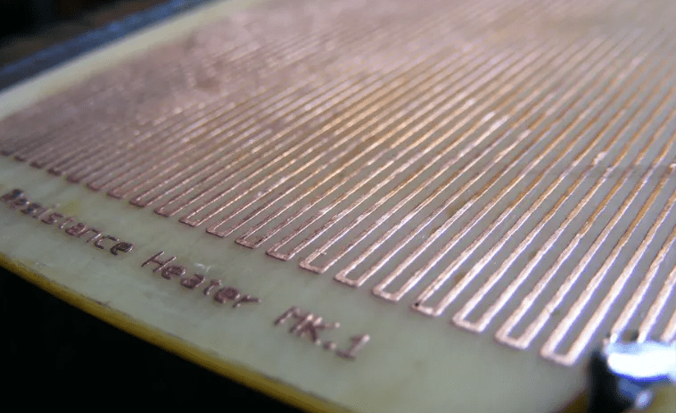
- Heating Element / Resistive Circuit
- This is the core component. It typically employs thick copper traces (e.g., 2oz, 3oz, or thicker) to form special circuit paths. These wide, thick copper traces possess specific resistance, and when current passes through, they generate heat according to Joule’s Law (P = I²R).
- Sometimes, discrete resistive elements (such as chip resistors or metal film resistors) are soldered onto the PCB to act as the heat source.
- Control Circuit
- Microcontroller: Units like Arduino, ESP32, or dedicated MCUs act as the “brain,” providing precise temperature control based on preset programs or sensor feedback.
- Power Drive Components: Such as MOSFETs or relays, are used to switch or regulate the high current flowing to the heating element.
- Temperature Sensors: Most commonly thermistors or digital temperature sensors (like DS18B20), used for real-time monitoring of the PCB’s temperature, providing data feedback to the microcontroller for closed-loop control.
- Power Interface
- Used to connect an external power source (e.g., DC 12V/24V or AC mains) to supply power to the entire system.
- Insulation and Protective Layers
- Solder Mask: Covers the circuit board to prevent short circuits and oxidation.
- Coverlay or Thermally Conductive Silicone: In some applications, a layer of insulating but thermally conductive material covers the heating area to protect the circuit and ensure even heat distribution.
- Safety Components: Such as fuses or thermal fuses, which cut off the circuit in case of overheating or overcurrent to ensure safety.
What is the Difference Between Convection and Infrared Preheaters in Heater PCBs?
Here is a comparison of these two types of heater PCB preheating systems:
Convection Preheaters
These systems feature two convective heating zones that transfer heat evenly and gradually to prevent thermal stress.
They also allow for process monitoring during operation. They typically integrate a thermocouple which analyzes the thermal environment and helps protect nearby components.
Infrared Preheaters
Infrared preheaters are beneficial for anyone needing to heat miniature printed circuit boards.
They incorporate a high-capacity infrared lamp that responds quickly and uniformly to deliver maximum heating efficiency.
Two Important Parts within a PCB Heater (Component Context)
In electronics, a heating element on a PCB is a component that generates heat. Two fundamental parts related to its operation are the Resistor and the Heat Sink.
- Resistor
- This is the component that enables the heater element to function. It also acts as a current limiter, preventing excessive current flow through the device which could cause damage.
- Resistors are made from conductive materials (like copper alloys or specialized resistive materials) with a specific resistance value. The amount of current flow depends on this resistance value.
- They are used to limit the current flowing through the heating trace; without them, the heater could burn out rapidly.
- Heat Sink
- This is a large, flat surface made of metal with high thermal capacity, used to dissipate heat generated by electronic components like transistors, diodes, and integrated circuits (ICs) that may be part of the control system.
- Heat from these components is conducted to the metal case or an aluminum plate, often attached via screws to the heat sink. It is frequently used in conjunction with a fan to increase airflow around the board and its components.
What are the Advantages of Preheating with a Heater PCB?
When experts and enthusiasts hear terms like “temperature profile,” they often immediately think of reflow ovens for printed circuit boards.
It’s easy to visualize the four main temperature-controlled zones along the length of the oven. This process ultimately leads to precisely soldered PCBs.
Each stage is meticulously managed and fine-tuned through expertise and repetition. Furthermore, each stage contributes to improved solder joint quality and reduced defects.
On the other hand, other industrial soldering equipment might not offer such precise temperature control. However, the preheating step is a commonality among them.
The role of the preheating stage is to gradually raise the temperature of the entire assembly. It accomplishes this by increasing the temperature from ambient to a soak temperature just below the melting point of the solder paste, typically around 150°C.
The temperature rises and falls at a constant rate of a few degrees per second. Subsequently, the preheating stage is followed by a soak stage, where the temperature is maintained for a period to ensure the PCB has a uniform temperature.
Next, the reflow step begins, initiating the solder joint formation process. Volatile solvents in the solder paste are burned off, and flux activity occurs during these stages.
What is the Design Process for a Heater PCB?
Designing a heater PCB is a straightforward process that requires you to outline a basic layout of the parts used in its creation.
The first step involves drawing the schematic diagram for the heater PCB. The next stage involves creating the board layout where the circuit will be printed.
Afterwards, you can use the toner transfer method to transfer the design onto the board. This involves printing the schematic onto special paper, placing it on the copper board, and using heat from an iron to transfer the toner.
The next step is to submerge the board in water and then rinse it to remove the paper template. Subsequently, you use items like steel wool to eliminate any remaining residue from the board.
Following this, the board is cleaned with an acetone solution to ensure no toner residue remains. Drilling holes in the board is the next objective, achievable using a standard drill or other suitable tools; for instance, a 1.0mm drill bit can be used for two or three holes.
Alternatively, a screwdriver or other suitable tool can be used to make appropriate holes. It’s also necessary to check the board’s continuity after drilling.
Furthermore, you can measure the board’s resistance and compare the results before and after the heating process. Finally, a high-current power supply can be used to evaluate the heating performance.
What Important Factors Should Be Considered When Creating Micro Heaters in a Heater PCB?
When designing the heater traces on a PCB, the length and arrangement of the traces are crucial.
For instance, you can create a PCB trace with a width of 0.254 mm and a length of 2 meters. Choosing between heater size and trace spacing measurements is easier because they are indirectly related.
This means that when the heater PCB size increases, the traces must also be longer, which can compromise heating uniformity. An example is when you need to create a smaller heater PCB, about 5 cm in size.
In this case, the traces need to traverse back and forth across this ~5 cm distance. For a 2-meter long total trace path, you would need approximately 40 passes.
If you space them 2 mm apart, the final heated area of the PCB will be close to 8 cm long. Furthermore, when you increase the trace length, you will require a higher voltage to achieve a similar temperature increase.
What are the Types of Heater PCBs?
These include:
- Single-Sided Heater PCB: This version has one copper conductive layer atop the substrate.
- Double-Sided Heater PCB: This type features conductive material on both the top and bottom sides.
- Multilayer Heater PCB: This version contains three or more conductive layers.
- Rigid Heater PCB: This is a heater PCB that cannot be folded or twisted, as its substrate is rigid.
- Flexible Heater PCB: This is a heater PCB that can be folded or bent.
- Rigid-Flex Heater PCB: This is a combination of rigid and flexible heater PCB sections.
What Components are Found within a Heater PCB System?
These include:
- Resistor: Limits current flow by releasing electrical energy as heat.
- Capacitor: Temporarily holds an electrical charge, releasing it only when needed by other parts of the circuit.
- Inductor: Stores energy as a magnetic field, which is created when current flows through it.
- Transformer: Transfers electrical energy from one circuit to another by increasing or decreasing voltage.
- Diode: Allows current to move linearly (i.e., from anode to cathode).
- Transistor: Amplifies charges or acts as a switch.
- Battery: Provides voltage to the heater PCB system.
Summary
A Heater PCB is a circuit board that perfectly integrates heating functionality with electronic control circuitry. It is not merely a “heating wire,” but rather an intelligent, efficient, and reliable “heating system solution.” Its core value lies in transforming the heating function from a traditional, bulky, discrete component format into a highly integrated, programmable, and easily installable flat module.


0 Comments