




PCB adhesives are bonding materials selected for a particular job in an electronic assembly. They may hold a component in place, support a cable, attach a heat sink or form a designed electrical connection. Those jobs do not call for the same properties. A glue that transfers heat is not necessarily electrically conductive, and an adhesive used before soldering is not automatically a substitute for solder.
Start with the joint you need to make, then choose the material and a process that can cure and verify that joint. The useful purchasing unit is not simply a tube of “PCB glue”: it is an approved material, location, quantity, cure process and acceptance requirement.
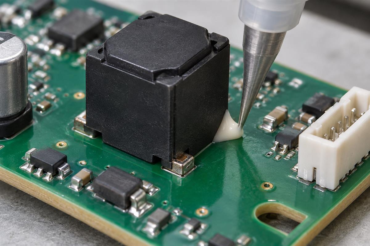
Choose PCB Adhesives by the Job They Must Do
Define the primary function before comparing adhesive families. Otherwise, a strong bond can still be the wrong bond: it may conduct electricity where insulation is needed, obstruct a connector or make a serviceable part impossible to replace.
| Required job | What the material must accomplish | What it does not automatically provide |
|---|---|---|
| Hold SMDs before a soldering operation | Maintain position through the specified handling and soldering sequence | The electrical solder connection; solder-mask coverage |
| Stake a component or secure a wire | Support the intended load without damaging the component, board or joint | A repair for an already cracked solder joint |
| Bond a heat sink | Attach the surfaces and support the required heat-transfer path | Electrical isolation unless specified and verified |
| Make an adhesive electrical connection | Provide the designed contact geometry and electrical performance | A drop-in replacement for every soldered joint |
| Reinforce beneath or around a package | Meet the package-specific flow, stress and cure requirements | The suitability of a general-purpose staking glue |
For a real example, Henkel’s LOCTITE 3609 data sheet describes a one-component, heat-cured epoxy for holding surface-mounted devices before wave soldering. The adhesive fixes position; solder still makes the intended soldered connection. Do not call that red adhesive “red solder mask.” The two materials have different jobs.
Likewise, a conformal coating is selected as a protective film and a potting compound fills a defined volume. A formulation may support several uses, but the application must be approved. Do not assume that a structural adhesive, coating and potting resin are interchangeable merely because each can contain epoxy or silicone.
Specify the Bond Before Comparing Resin Families
A material shortlist needs the actual surfaces, loads and operating conditions. Labels such as epoxy, silicone or acrylic describe chemistry, not a complete performance specification.
- Bonded surfaces: identify solder mask, exposed metal, component molding compound, cable jacket or heat-sink surface. A bond to solder mask also depends on that mask remaining attached to the board.
- Mechanical task: define the movement or load to control. Avoid blocking an electrolytic capacitor’s pressure vent or loading a delicate component body simply to make a large adhesive fillet.
- Electrical role: state whether the joint must insulate or conduct. Keep adhesive away from contacts and test points unless the design explicitly calls for it there.
- Thermal conditions: separate assembly exposure from service temperature and thermal cycling. A brief cure temperature is not a continuous-use rating.
- Environment: identify humidity, condensation, cleaning fluids and relevant chemical exposure. Use the product’s actual compatibility evidence.
- Maintenance: decide whether the bonded part must be removed later. Specify the allowed removal method before encapsulating accessible joints.
Epoxy products are useful candidates for many bonding tasks, but they are not all rigid, high-temperature or optically clear. Silicone formulations can offer compliant joints, but the exact grade and its compatibility still matter. Choose the documented product, not a universal property assigned to the family.
Example: a tall component needs support against movement. The first decision is where force should transfer to the board and what must remain accessible. Only then can the team compare a compliant staking material with a more rigid candidate. Covering the whole component with the strongest available adhesive avoids neither stress nor service problems by itself.
Match the Cure Mechanism to the Actual Assembly
The adhesive must reach its specified cure condition throughout the required bond. A fast advertised cure is irrelevant if the assembled geometry prevents heat, light or moisture from reaching the necessary region.
Heat cure: measure the assembly, not just the oven setting
The LOCTITE 3609 sheet explicitly measures cure time from when the adhesive reaches the cure temperature; oven residence can be longer because the assembly needs to warm up. Use this as a process lesson, not a universal recipe. Confirm the current product instructions and check that every component and board material can tolerate the proposed profile.
Two-part systems: distinguish mixing ratio from cure conditions
MG Chemicals’ 8329TFS data sheet gives a useful counterexample to the assumption that all two-part epoxies cure at room temperature. It specifies heat cure and lists a 1:1 ratio by volume but 1:0.96 by weight. For that ratio, 10 g of part A calls for 9.6 g of part B, not 10 g. These numbers belong to that product and revision, not other adhesives.
The same product is described as thermally conductive and electrically insulating. Heat transfer and electrical conduction must therefore be separate selection fields. Check the current data sheet, safety sheet and the requirements of the actual joint before use.
Light cure: account for hidden adhesive
An opaque package or heat sink can shade the bond. Master Bond’s UV-system guidance explains that designated UV/heat dual-cure products address concealed regions. This does not mean any UV adhesive can be cured by adding heat. Choose a documented mechanism and verify the assembled geometry, exposure and secondary-cure requirements.
Moisture cure: do not equate a surface skin with a finished joint
Dow’s electronics adhesive range includes one-part moisture-cure products. Ask the manufacturer how bead depth, access and conditions affect the proposed application. Do not approve a deep or enclosed bond merely because an exposed bead looks dry.
Control Dispensing, Placement and Cure as One Process
A repeatable bond requires control from material preparation to final cure. Use the exact product instructions as the process source; the sequence below identifies the decisions to document rather than supplying a universal temperature, cleaning solvent or dot size.
- Release the correct material. Check grade, lot, shelf life and storage history. Follow any required conditioning procedure. Do not assume every adhesive belongs in a refrigerator or that an expired cartridge is acceptable because it still flows.
- Prepare compatible surfaces. Remove the contamination identified by the validated cleaning process and allow the required drying. Confirm compatibility with solder mask, plastics and markings before applying a solvent across the board.
- Set the dispense and keep-out limits. Mark where adhesive may go and where it must not go. Establish a deposit that contacts the intended surfaces after placement without reaching pads, connector contacts, vents or test points.
- Place and hold the part. Verify the gap, alignment and fixture. Include the delay between dispensing and placement within the permitted working time. Inspect displacement and squeeze-out on representative samples.
- Cure, then release for the next operation. Record the required profile or exposure and the defined release criterion. A part staying in place during handling does not by itself demonstrate final cure or service strength.
For a hypothetical heat-sink bond, the deposit and final gap must be controlled together. A large bead may spread beyond the intended interface when the sink is seated. A tiny bead may leave poor contact. Establish the acceptable result with the actual surfaces and assembly fixture instead of transferring a dispensing time from a different board.
Observe the product safety data sheet and workplace controls for handling, ventilation and curing equipment. The board should be unpowered during this work. Do not use an unspecified household adhesive on a production or safety-critical assembly simply because it sticks in a bench trial.
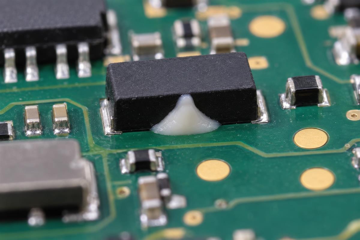
Validate the Joint, Not Just the Glue Data Sheet
Qualification must show that the complete joint performs in its intended environment. A supplier’s material test on a particular specimen does not establish acceptance for your solder mask, component body or bond geometry.
| Observation | What to investigate | Useful evidence before release |
|---|---|---|
| Adhesive separates cleanly from a surface | Contamination, surface compatibility, preparation and actual cure | Controlled samples using the intended production surfaces |
| Board coating or component surface comes away with the adhesive | The underlying surface or load path, not just adhesive strength | Failure-location record and design review |
| Material remains soft where a hard cure is expected | Ratio, mixing, material age, exposure and hidden regions | Validated cure evidence for the actual formulation |
| Glue reaches contacts or blocks access | Deposit, placement gap, flow and working time | First-article photos and documented keep-out checks |
| Assembly passes initially but fails after exposure | Joint behavior under the relevant heat, humidity, vibration or chemicals | Application-specific qualification results and acceptance limits |
Make the acceptance plan explicit: which joints are inspected, which samples are tested, which loads or exposures apply, and who approves the result. Do not invent a single push-off force or insulation value for every assembly. The appropriate test depends on the function and product requirements.
For an insulating bond, assess the required electrical isolation in the actual construction. For an electrically conductive bond, assess the connection resistance and stability required by the circuit. For a thermal joint, evaluate the assembled heat path under defined operating conditions. None of these is established by the word “conductive” alone.
Changes in adhesive grade, substrate finish, dispensing setup or cure equipment may require reassessment. Keep the approved configuration tied to the board and assembly revision so a purchasing substitution does not silently invalidate the process.
Send an Adhesive Specification the Assembler Can Follow
A useful assembly instruction names the material and makes its application inspectable. “Glue the large parts” is not enough to reproduce or approve a production build.
| Include | What the assembler needs |
|---|---|
| Material identity | Approved manufacturer and grade, applicable documents, substitution approval rule |
| Application drawing | Component references, adhesive locations, bonded surfaces and keep-outs |
| Joint geometry | Required gap or deposit/fillet limits established during validation |
| Process controls | Preparation, mixing where applicable, working time, placement and cure instructions |
| Acceptance | Inspection method, test requirements, limits and handling-release condition |
| Traceability and service | Lot and process records, approved rework/removal method, change control |
For PCB assembly discussions, provide the BOM, placement data, assembly drawing, adhesive requirements and relevant environmental or test conditions. If the material is not yet selected, identify the unresolved function and process constraints rather than inserting an arbitrary brand into the BOM.
Send the package through PCBtry’s contact page and ask which dispensing, curing and verification requirements can be supported for the specific job. Confirm feasibility and acceptance details before production; a quotation is not a substitute for material qualification.
Frequently Asked Questions
Are PCB glue and PCB adhesive different materials?
The names alone do not establish a difference. Use the exact product identity, intended function and approved process rather than treating either label as a material specification.
Is SMT red glue the same as solder mask?
No. SMT adhesive holds components in a specified assembly sequence. Solder mask covers selected board surfaces while leaving required soldering areas exposed. Color does not make the products interchangeable.
Can PCB adhesive replace solder?
Only a designed and qualified conductive-adhesive interconnection can perform that electrical role. Mechanical staking glue cannot repair the electrical continuity of a failed solder joint.
Does thermally conductive mean electrically conductive?
No. They describe different properties. Check both requirements independently and verify the selected grade’s documented behavior in the intended assembly.
Can I cure any UV adhesive under an opaque component?
Do not assume so. Identify the shadowed region and select an approved cure mechanism for it. A product with a documented secondary cure is different from a light-only formulation.
Is the strongest adhesive always the safest choice?
No. The load can move into the board coating or component body, and an inflexible joint can conflict with the design’s movement or service needs. Qualify the whole joint.
Can I remove cured adhesive with any solvent?
No. Identify the material and obtain a compatible rework procedure. A solvent or heat treatment that attacks glue may also damage the board, components or markings. Do not pry against pads.
What evidence should accompany an adhesive substitution?
Request the proposed grade, technical and safety documents, differences from the approved material, process changes and applicable validation results. Obtain the designated approval before using it in production.



0 Comments