




An LED PCB is a printed circuit board that supports and electrically connects light-emitting diodes. Depending on the design, it also provides a path for heat to leave the LED. The board may use FR4, an insulated metal substrate such as aluminum-backed laminate, or another construction selected for the application. An LED PCB is not automatically a complete lamp: LEDs, current control, cooling and protection must all be included in the right places.
Start by separating three questions: What are you buying? Where will the heat go? What must be checked before the assembly can be powered? Those questions prevent more expensive mistakes than choosing a board simply because its underside looks metallic.
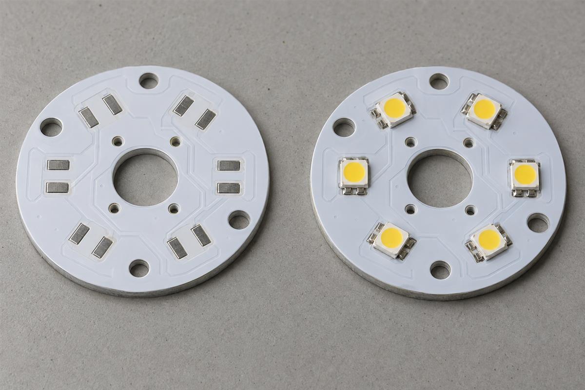
What Does an LED PCB Include?
The term can mean either an unpopulated board or a board with LEDs already soldered onto it. Confirm the delivery scope before comparing prices. Two suppliers can quote an “LED PCB” while offering different products.
| Item | What it normally contains | What you still need to establish |
|---|---|---|
| Bare LED PCB | Patterned copper, substrate, solderable pads and specified markings | Who buys and assembles the LEDs and other components? |
| Populated LED board | The PCB plus the components listed in the assembly BOM | Does it include current regulation, connectors and protection, or only the LED array? |
| LED driver | Circuitry that provides the specified electrical operating conditions | Does its current, output-voltage range and dimming interface match the array? |
| Finished lighting product | The agreed combination of electronics, enclosure, optics, cooling and wiring | Which safety, environmental and performance tests apply to the complete product? |
For example, a circular board carrying twelve LEDs may still require an external constant-current driver and a heat sink. Its round shape, white solder mask and connector do not prove that it can be attached to an arbitrary power supply. Conversely, a strip designed for a specified constant-voltage input may include current-limiting components. Read the actual schematic and input specification instead of inferring the supply from appearance.
Also distinguish the LED package from the board. The package contains the light-emitting semiconductor and its connections; the PCB routes power between packages and other components. A package’s thermal pad may have a specified electrical connection or may be isolated. Use that exact part’s documentation, not the footprint of a similar-looking LED.
Which Board Material Fits the LED Application?
Choose the construction from the electrical layout, heat load, mechanical shape and required insulation. There is no universal wattage at which every LED design must switch from FR4 to aluminum. Package construction, copper area, the enclosure and ambient temperature change the answer.
| Construction | Why it may fit | What can make it unsuitable | Check before release |
|---|---|---|---|
| FR4 rigid PCB | Combines LEDs with routing and control circuitry; thermal vias can help appropriate designs | An inadequate path from the package into the board and onward to cooling | Package land pattern, copper/via arrangement and measured operating temperature |
| Aluminum-backed insulated metal substrate | Provides a metal heat-spreading base under an electrically insulating dielectric | Poor dielectric selection, routing constraints or ineffective contact to the heat sink | Specified dielectric, copper, base thickness, mounting and insulation requirements |
| Flexible circuit | Fits curved or space-constrained lighting arrangements | Bending that damages copper or solder joints; no adequate heat-removal route | Installed bend geometry, component-free bend areas and mounting surface |
| Specialized ceramic construction | May meet demanding thermal or electrical requirements | Different processing, mechanical handling and cost requirements | Exact ceramic system, metallization, assembly process and supplier capability |
In a common single-sided insulated metal substrate, the stack is copper circuit, dielectric and metal base. The dielectric must electrically separate the circuit from the base while allowing heat transfer. “Electrically insulating” does not mean “designed to block heat.” Henkel’s Bergquist LED thermal-material guide illustrates this distinction. Do not assume every metal-core board uses the same dielectric or construction.
Ask for the actual laminate designation rather than “good thermal aluminum.” Thermal conductivity, measured in W/m·K, describes a material. Thermal resistance, measured in K/W or °C/W, describes a heat-flow path under defined conditions. Layer thickness, effective area and interfaces matter too; comparing conductivity numbers alone does not compare finished lamps.
Cree LED’s PCB thermal-management application note describes FR4 thermal-via options for certain LED families and states limitations. It supports evaluating FR4, not a blanket claim that every LED package can use the same via pattern. Follow the chosen package’s land-pattern and assembly recommendations.
How Does Heat Leave the LED?
Heat must travel from the junction inside the LED through its package and mounting connection, into the PCB, through any interface material and heat sink, and finally into the environment. A good board cannot compensate for every poor connection later in that path.
Think of a metal-backed board screwed to a housing. If the board does not sit flat or the specified interface is missing, the metal base can spread heat without transferring it effectively to the housing. Check the contact arrangement as well as the laminate. Lumileds’ practical thermal-design guidance treats the complete thermal system, rather than the PCB in isolation.
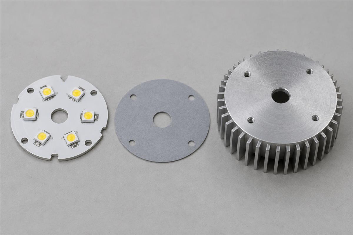
A simple temperature-rise example
For a simplified steady-state model, temperature rise equals heat flow multiplied by thermal resistance: ΔT = Q × Rθ. Suppose a single heat source dissipates 2 W as heat and its effective junction-to-ambient thermal resistance is 15 K/W. The predicted rise is 30°C. At 40°C ambient, that model predicts a 70°C junction temperature.
These are illustrative inputs, not LED ratings or measured results. The 2 W is heat, not necessarily electrical input power; some input leaves as light. The 15 K/W must represent the entire path for the stated installation. Multiple LEDs share board and heat-sink temperatures, so calculating each as an isolated device can underestimate heating. Verify the model with the LED manufacturer’s temperature-measurement method and the actual enclosure, drive current and ambient conditions.
What should you measure?
Record the operating current, ambient temperature, mounting configuration, stabilization condition and the manufacturer’s specified temperature-reference location. Use the package’s appropriate thermal data to estimate junction temperature where required. A handheld reading from an arbitrary shiny surface is not a direct junction-temperature measurement.
Compare the result with the exact component’s operating limits and the application’s reliability target. A maximum junction rating is not a promise of useful lifetime at that temperature. If temperature is excessive, investigate the path, reduce the heat load or revise the cooling design before increasing current to recover brightness.
How Is an LED PCB Made and Assembled?
Fabrication creates the unpopulated board; assembly attaches the LEDs and other parts. The following sequence describes the handoffs. Individual fabrication operations vary with the approved stack-up and factory process, so it is not a universal machine-by-machine routing sheet.
- Release the electrical and mechanical design. Confirm LED part numbers, polarity, array connections, driver interface, mounting holes and cooling contact. Deliver fabrication data and an approved drawing. Resolve contradictions between the drawing, copper files and component land patterns before production.
- Select and approve the board construction. Agree the substrate, dielectric where applicable, copper thickness, finished thickness and surface finish. For an insulated metal substrate, “aluminum” alone is incomplete: the dielectric and insulation requirements are part of the specification.
- Fabricate the bare circuit board. The manufacturer forms the copper pattern and performs the required hole, interconnection, mask, finish and outline operations for that construction. The deliverable is a board matching the released data, not a functioning light source. Check dimensions and bare-board electrical continuity/isolation against the agreed requirements.
- Prepare the assembly materials and process. Match the BOM to the correct LED ordering codes, approved substitutions and any specified color or output bins. Prepare placement data, polarity references and a paste/reflow process compatible with the components and board. An apparently equivalent package may differ in pad arrangement or optical characteristics.
- Place, solder and inspect the components. Assemble the board using the qualified process. Check orientation, alignment and solder joints; use additional inspection where hidden connections and product risk require it. Do not invent a universal reflow peak temperature or solder-void acceptance percentage for every LED package.
- Test the assembled module in its defined configuration. Verify electrical operation at the specified input, then perform the agreed optical and thermal checks. A board that lights briefly has not demonstrated steady-state thermal performance, color consistency, enclosure protection or product compliance.
For fabrication control points, see the LED PCB manufacturing process. For component handling, placement, soldering and assembly-stage checks, use the separate LED PCB assembly process. These deeper workflows begin where this introductory overview leaves off.
What Should You Check Before Ordering an LED PCB?
Send enough information for the manufacturer to distinguish a board quote from a tested module quote. The checklist below can accompany a drawing release or be used to compare two proposals with the same scope.
| Send or confirm | Why it matters | Acceptance question |
|---|---|---|
| Gerber or agreed fabrication files, drill data and dimensioned drawing | Defines copper, holes, outline, mounting and tolerances | Do the released files and drawing describe the same revision? |
| Stack-up, material designation and finish | Prevents an unspecified laminate substitution | Which properties and substitutions require approval? |
| BOM, placement data and LED datasheets | Defines actual parts, orientation and package requirements | Are ordering codes, polarity references and bin requirements explicit? |
| Electrical input, driver and dimming requirements | Defines how the assembly will be operated | Who supplies current control and verifies the driver/array match? |
| Heat-sink interface, enclosure and ambient conditions | Makes thermal evaluation representative | Will testing use the final mounting arrangement or a documented fixture? |
| Inspection and electrical/optical/thermal test plan | Separates visual inspection from demonstrated performance | What are the pass/fail limits, sample plan and supplied records? |
| Quantity, revision and delivery scope | Makes price and lead-time comparisons meaningful | Does the quote cover bare boards, assembly, testing and required accessories? |
Ask which requirements are verified at board level and which belong to the finished product. Bare-board electrical testing does not certify light output. Solder inspection does not prove thermal performance. Neither a metal substrate nor white solder mask makes a module waterproof or compliant with a lighting safety standard.
For a board review, send PCBtry your fabrication files, drawing and required construction. For an assembled-module review, add the BOM, placement data, LED datasheets, driver conditions and test requirements through the contact page. State which items are still undecided so the review can identify missing inputs before a production quote is finalized.
LED PCB Questions
Is every LED PCB an aluminum PCB?
No. LED PCB describes its application, not one substrate. FR4, insulated metal substrates and other constructions can support LEDs. Choose from the electrical, thermal and mechanical requirements, then verify performance in the intended installation.
Can I connect an LED board directly to a battery?
Only when the module is explicitly designed for that battery’s voltage range and has the necessary current control and protection. A bare LED array is not automatically battery-ready. Check the schematic and rated input before connecting it; use a suitably current-limited test setup and competent supervision where needed.
Does the aluminum base carry the LED current?
In a conventional insulated metal substrate, the patterned copper carries the circuit connections and the dielectric separates it from the metal base. Special constructions exist, so confirm the actual stack-up and grounding scheme. Do not assume a mounting screw or exposed metal edge is an intended electrical terminal.
Does a metal-backed board eliminate the heat sink?
Not necessarily. It may spread heat effectively but must still transfer that heat to its surroundings. Whether separate cooling is needed depends on dissipation, exposed area, airflow, enclosure and allowed temperature. Validate the complete installation rather than judging the metal thickness alone.
Why are many LED boards white?
White solder mask is often selected for optical and appearance reasons. Its color is not proof of thermal conductivity, electrical insulation performance or environmental protection. Specify the mask properties that matter to the application and validate optical behavior in the actual assembly.
Are an LED PCB and an LED driver PCB the same thing?
They may be separate boards or share one assembly. The LED board supports the emitters; the driver circuitry controls their operating conditions. TI’s TIDA-01581 reference design illustrates current control, dimming and thermal protection in a specific driver. Its test results are not certification for another board.
Do LED circuits produce no electromagnetic interference?
That is not a safe general claim. Switching drivers, dimming edges, wiring and layout can affect emissions. Evaluate the complete powered system against its applicable requirements. Changing the LED substrate alone does not demonstrate electromagnetic compatibility.
What proves that an LED board is ready for production?
A released design, agreed materials and components, an assembly process, and inspection/test evidence against defined acceptance criteria. A photograph of illuminated LEDs is insufficient. Confirm the revision, test conditions and outstanding deviations before approving production.



0 Comments