
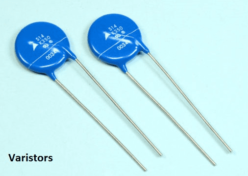
The image above shows a real varistor. You might mistake them for capacitors. However, varistors and capacitors don’t have much in common besides their size and design.
Varistors are used to suppress voltage surges, a function capacitors cannot perform.
A varistor is a resistor whose resistance changes with the voltage applied across it. Its name comes from combining “variable” and “resistor.” They are also called VDRs (Voltage Dependent Resistors) and have non-Ohmic characteristics, placing them in the category of nonlinear resistors.
Unlike potentiometers and rheostats, where resistance is manually changed between a min and max value, a varistor’s resistance changes automatically based on the applied voltage. A varistor contains two semiconductor elements and functions similarly to a Zener diode, providing overvoltage protection for circuits.
So, how does a change in applied voltage alter its resistance? The answer lies in its composition. Being made of semiconductor material, its resistance decreases as the voltage increases. When the voltage rises excessively, its resistance drops significantly. This property makes it ideal for protecting sensitive circuits from overvoltage.
How Varistors Work
To explain how a varistor works, let’s use the characteristic curve shown in the figure below for better understanding.
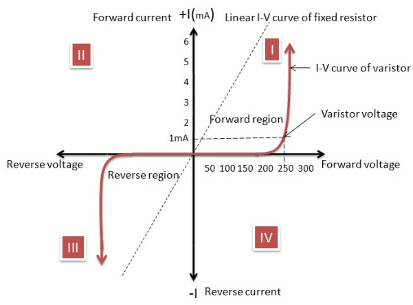
The V-I characteristic curve of a varistor is similar to that of a Zener diode. It’s essentially bidirectional, as we can see it operates in both the first and third quadrants. This characteristic makes it suitable for circuits connected to either AC or DC power sources. It’s particularly well-suited for AC power because it works with either direction or polarity of the sine wave.
The clamping voltage (or varistor voltage) shown in the graph is defined as the voltage across the varistor when the current through it reaches a very low value (typically on the order of a few milliamps). This current is usually called the leakage current. This value of leakage current exists because the varistor has a high resistance value when the clamping voltage is applied across it.
Now, examining the V-I characteristic, we see that when the voltage across the varistor increases beyond the clamping voltage, the current increases suddenly.
This happens due to a sudden drop in resistance caused by the avalanche breakdown phenomenon. Above the threshold voltage (in this case, the clamping voltage), electrons start flowing rapidly, reducing the resistance and increasing the current through the varistor.
This helps with voltage transients. When a circuit experiences a high transient voltage, the voltage across the varistor increases to a value greater than its rated (clamping) voltage, thereby increasing the current and causing it to act like a conductor.
From the varistor’s V-I curve, you can see that even as the current increases, the voltage across the varistor remains almost equal to the clamping voltage. This means it acts like a self-regulator even during a voltage transient, making it even more suitable for such situations as it controls the voltage rise.
The steep nonlinear curve indicates that a large excess current can pass through the varistor within a very narrow voltage range (showing its self-regulating property), clipping off any voltage spikes.
Varistor Symbol
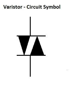
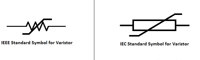
Initially, varistors were represented as two diodes connected back-to-back (anti-parallel), as shown in the figure, because they exhibit diode-like characteristics in both current directions. However, this symbol is now commonly used for the DIAC (Diode for Alternating Current). In modern circuits, the symbol for a varistor is shown as below.
You might wonder, how does a varistor help suppress voltage transients in a circuit? To understand this, we first need to know where voltage transients come from. The sources of voltage transients in circuits and power supplies can be internal to the circuit itself or from any external source, regardless of whether it’s an AC or DC supply. These transients can cause voltages to spike to thousands of volts, which can have disastrous consequences for the circuit. Therefore, suppressing these voltage transients is necessary.
AC Waveform Transient
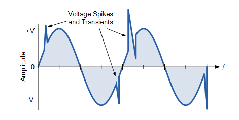
The varistor is connected across the main power supply lines – Line and Neutral or Line-to-Line for AC supply, and Positive and Negative lines for DC supply – with a rated voltage matching its application. Varistors can also be used for DC voltage stabilization, especially for protecting electronic circuits from overvoltage pulses.
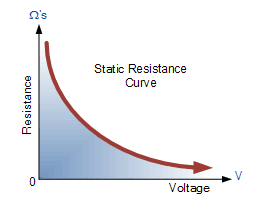
Static Resistance
Under normal operating conditions, a varistor has a very high resistance (hence the name), functioning similarly to a Zener diode by allowing voltages below its threshold to pass through unaffected.
However, when the voltage across the varistor (of either polarity) exceeds the varistor’s rating, its effective resistance decreases sharply as the voltage increases, as shown in the figure.
According to Ohm’s law, for a fixed resistor where resistance R remains constant, the current-voltage (I-V) characteristic is a straight line. Here, the current is proportional to the potential difference across the resistor.
But the I-V curve for a varistor is not a straight line because a small change in voltage causes a significant change in current. A typical standardized voltage-current characteristic curve for a standard varistor is shown below.
Characteristic Curve
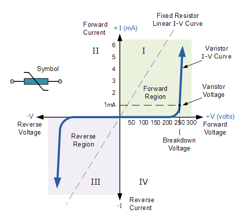
As seen above, the varistor has a symmetrical, bidirectional characteristic, meaning it operates in both directions of the sine wave (first and third quadrants), behaving like two Zener diodes connected back-to-back. When the varistor is not conducting, the I-V curve is linear because the current flowing through the varistor remains constant and low, merely a few microamps of “leakage” current. This is due to the varistor’s high resistance acting like an open circuit, remaining constant until the voltage across it (either polarity) reaches a specific “rated voltage.”
The rated voltage or clamping voltage is the voltage across the varistor measured at a standardized DC current of 1mA. That is, the level of DC voltage applied to its terminals that allows 1mA of current to flow through the varistor’s body, whose resistance depends on the material used in its construction. At this voltage level, the varistor begins to transition from an insulating state to a conducting state.
When the transient voltage across the varistor equals or exceeds the rated value, the resistance of the device suddenly becomes very small due to the avalanche effect in the semiconductor material, and the varistor becomes a conductor. The small leakage current flowing through the varistor increases rapidly, but the voltage across the varistor is limited to a level just above the varistor voltage.
In other words, the varistor self-regulates the transient voltage across it by allowing more current to flow through it. And due to its steep nonlinear I-V curve, it can deliver vastly different currents over a narrow voltage range, thereby clipping any voltage spikes.
Varistor Capacitance
Because the dominant conductive region between the varistor’s terminals acts like a dielectric at voltages below the clamping voltage, the varistor behaves more like a capacitor than a resistor under these conditions. The capacitance value of each semiconductor varistor is proportional to its area and inversely proportional to its thickness.
When used in DC circuits, the capacitance of a varistor remains roughly constant as long as the applied voltage does not exceed the clamping voltage level, and it drops suddenly as it approaches its maximum rated continuous DC voltage.
However, in AC circuits, this capacitance affects the device’s bulk resistance within the non-conducting leakage region of the I-V characteristic. Since varistors are typically connected in parallel with electrical equipment to protect it from overvoltage, the leakage resistance of the varistor decreases rapidly with increasing frequency.
This relationship is approximately linear with frequency, and the resulting parallel resistance, its AC reactance X_C, can be calculated using the standard formula for capacitors: 1/(2πƒC). As frequency increases, its leakage current also increases.
Besides silicon-based semiconductor varistors, Metal Oxide Varistors (MOVs) have been developed to overcome some limitations of Silicon Carbide (SiC) varistors.
Types of Varistors
The type of varistor depends on the material used for its body. The two most common types are discussed below.
- Silicon Carbide (SiC) Varistors: As the name suggests, the body of these varistors is made from Silicon Carbide. They were widely used before the newer Metal Oxide Varistors (MOVs) became available. Today, they are often used in high-power, high-voltage applications. A major drawback of this type is their relatively high standby current. Therefore, a series gap is sometimes needed to limit standby power consumption.
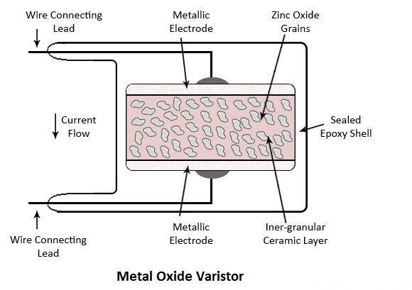
- Metal Oxide Varistors (MOV): Due to some significant drawbacks of SiC varistors, another type – the Metal Oxide Varistor – was developed. It offers excellent protection against voltage transients and is now very popular. Its body is made from metal oxides, primarily zinc oxide (ZnO) grains. These grains are pressed into a ceramic block, with about 90% being ZnO grains and 10% being other metal oxides like cobalt, bismuth, and manganese. This block is then sandwiched between two metal plates. The 10% mixture of other metal oxides acts as a binder, holding the ZnO grains firmly between the metal plates. Connecting terminals or leads are attached to the two metal plates.
The figure below shows the internal structure of an MOV.
The main advantage of MOVs over SiC varistors is their low leakage current. Under normal operating conditions, the leakage current of an MOV is very low. Furthermore, MOVs exhibit a highly nonlinear current-voltage characteristic.
One disadvantage of this type is that the surge current handling capability depends on the width of the transient pulse and the number of pulse repetitions. Thus, for transient pulses with larger widths, the surge current handling capability can decrease, potentially causing heating issues. However, this heating can be managed by dissipating the energy absorbed from the transient pulse.
What is the Role of a Varistor on a PCB?
Core Function: Transient Overvoltage Protection
The fundamental role of a varistor on a PCB is to absorb instantaneous overvoltages and pulse energy coming from external sources, thereby protecting the more precise and fragile circuit components downstream from damage.
Working Principle Summary:
- Under normal operation, when the voltage across the varistor is below its “varistor voltage” (threshold voltage), it presents a very high resistance (up to megaohm levels), acting essentially like an insulator. It has almost no effect on normal circuit operation, with only a very tiny leakage current.
- When a transient overvoltage (like a surge or electrostatic discharge – ESD) strikes and its value exceeds the varistor’s threshold, the varistor’s resistance drops dramatically (within nanoseconds), becoming almost like a conductor. It then quickly shunts the excessive current away from the protected chip or component, converting it into heat. This “clamps” the voltage between the circuit nodes to a relatively safe level.
- Once the overvoltage disappears, the varistor automatically returns to its high-resistance state.
Specific Voltage Transient Events it Protects Against:
Varistors primarily guard against these common threats:
- Lightning-Induced Surges: Not direct lightning strikes, but lightning activity can induce high voltage surges on lines (like power lines, communication lines).
- Electrostatic Discharge (ESD): Static electricity from human contact or equipment can create high-voltage pulses when discharging into a port.
- Inductive Load Switching: Inductive loads like relays, motors, and transformers can generate a high reverse electromotive force (voltage spike) when switched off.
- Grid Switching Overvoltages: Large switching operations in the power system can also cause surges.
Typical Application Scenarios and Connection on a PCB:
Varistors are typically connected in parallel across the circuit they need to protect.
- AC Power Input Ports:
- Connection: Connected between the Live (L) and Neutral (N) lines.
- Purpose: To absorb surges coming from the power grid, preventing them from impacting the downstream power supply module and the entire device.
- DC Power Entry Points:
- Connection: Connected between the DC positive (VCC) and negative (GND) rails.
- Purpose: To suppress overvoltages introduced via the DC power lines, protecting core chips on the board.
- Signal Ports / Data Lines:
- Connection: Connected between the signal line and ground, or between different signal lines.
- Purpose: To protect sensitive communication interfaces from ESD or external induced surges.
Key Advantages and Limitations of Varistors:
Advantages:
- Fast Response Time: Nanosecond-level response to transient overvoltages.
- High Surge Current Handling: Can withstand very large instantaneous currents, suitable for absorbing high-energy surges.
- Good Clamping Effect: Limits the voltage to a predetermined value.
- Low Cost and Simple Circuit Design.
Limitations (Important!):
- Aging/Degradation: Each large surge event causes slight degradation. After multiple strikes, it may fail (increased leakage current or even short circuit).
- Not for Sustained Overvoltage: If a continuous overvoltage is applied, it will absorb excessive energy, overheat, and potentially suffer thermal runaway, leading to burning or cracking. Therefore, they are often used in series with a fuse; if the varistor shorts, the fuse blows, disconnecting the faulty circuit.
- Inherent Parasitic Capacitance: Their capacitance value is relatively large, making them unsuitable for high-frequency signal lines as it can distort the signal.
Conclusion
The role of a varistor on a PCB is like an intelligent “voltage floodgate.” When the circuit is calm (normal voltage), it stays silent. But when a voltage “flood” (surge) hits, it instantly opens, diverting the dangerous energy away to protect the downstream “fields” (sensitive circuits). It is an indispensable component for product reliability and safety certification.


0 Comments