




A flexible PCB is a printed circuit built on a thin, bendable insulating material. Its patterned conductors connect components or electronic modules while the circuit fits a curved or folded space. Flexibility does not mean unlimited folding: a circuit installed in one fixed shape and a circuit that moves repeatedly require different mechanical designs and validation.
This distinction matters before you choose materials or request a quotation. Start with the job the circuit must perform, identify which areas may move, and define what would count as a successful prototype. The following guide explains the parts, construction choices and practical checks without treating one material name as a guarantee of reliability.
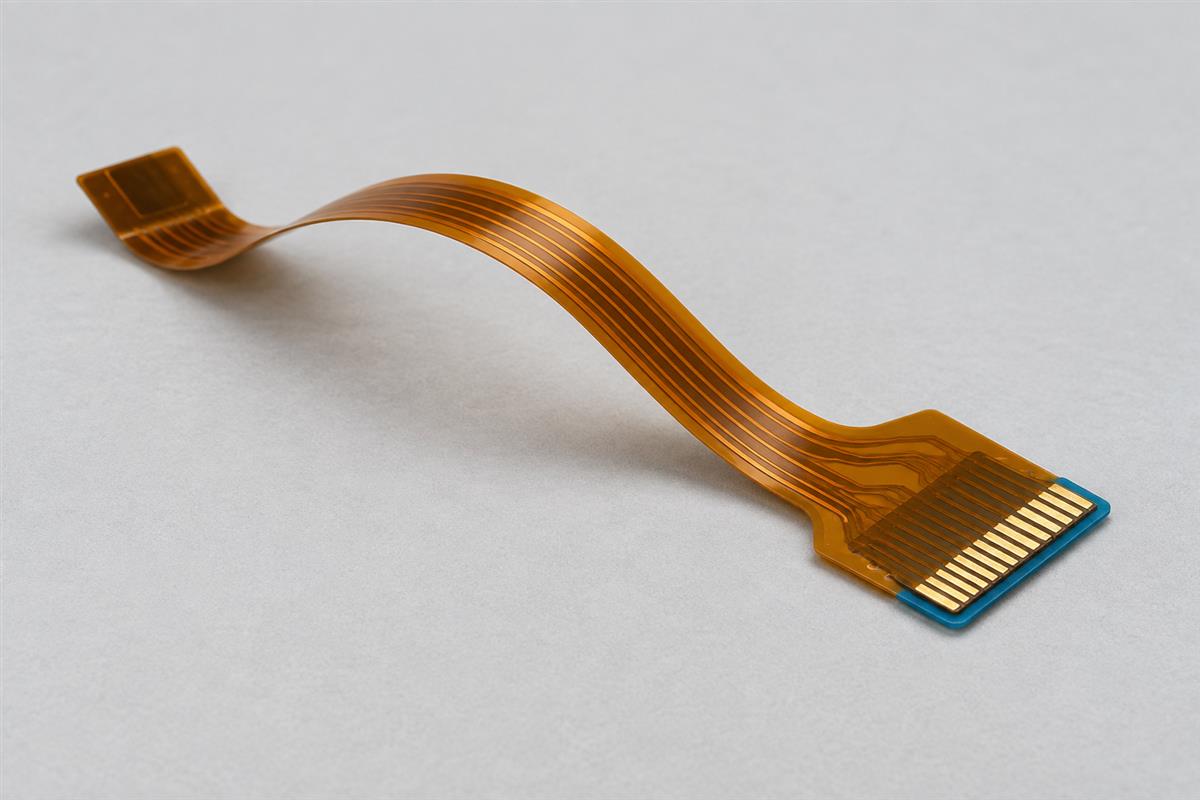
Understand the Parts of a Flexible PCB
A flex circuit is still a PCB. The difference from a conventional rigid board is its construction and mechanical behavior, not whether it contains printed conductors. Think of it as an electrical connection with a deliberately engineered shape, rather than a rigid board that you are allowed to bend.
| Part | What it does | What to identify on the drawing |
|---|---|---|
| Flexible dielectric | Insulates conductors and supports the circuit pattern. | Material grade and thickness, not just the color of the film. |
| Copper conductors | Carry signals and power. | Conductor layers, copper requirements and connections between layers. |
| Coverlay or other protective covering | Covers selected conductors while leaving connection areas accessible. | Cover material, openings and the areas requiring exposed pads. |
| Bonding layers, where used | Join parts of the construction. | Which interfaces use adhesive and which use an adhesiveless laminate construction. |
| Local stiffener | Supports a selected area such as a connector termination. | Location, thickness and the transition to the unsupported flex. |
Polyimide is one common dielectric, but its name alone does not specify the complete circuit. Copper, bonding materials, protective layers and local reinforcement all influence the finished part. An adhesiveless base laminate also does not mean that every interface in the completed assembly is adhesive-free.
For a simple example, imagine a flexible tail ending in exposed contacts. The contacts make the electrical connection; the film supports them; a local reinforcement may help the end meet the mating connector’s thickness and insertion requirements. That reinforcement is not another signal layer. Compare this with an integrated rigid-flex construction, where the rigid sections can contain their own routed copper layers.
The Minco Flex Circuits Design Guide, particularly its construction and materials sections, provides examples of these distinctions. Its listed manufacturing capabilities are supplier-specific, not universal specifications or a statement of PCBtry’s capabilities.
Separate Installation Bends From Repeated Motion
First decide whether the circuit changes shape only during installation or repeatedly during operation. A part that fits around a corner once has not thereby demonstrated that it can survive a moving hinge.
| Use pattern | Illustrative situation | Question to resolve |
|---|---|---|
| Bend to install | A tail is formed around a housing feature and secured. | Can it be installed, retained and serviced without a damaging bend? |
| Occasional repositioning | A service cover is opened during maintenance. | How many service operations are expected, and how is movement controlled? |
| Repeated motion | An interconnect moves whenever a mechanism operates. | What motion, cycle count, environment and electrical acceptance criteria must it survive? |
These are planning categories, not certified life ratings. Describe the actual movement even if a supplier uses different terminology. A small vibration at an unsupported connection can also matter; calling the main bend static does not describe every mechanical load.
Consider two hypothetical products using a similarly shaped tail. In one, the tail is secured after assembly. In the other, a door moves it every time the product is used. The outline may look identical, but the second design needs a defined motion envelope and repeated-motion validation. A photograph or a successful continuity check on a flat sample cannot establish that performance.
Minco’s flex-circuit FAQ likewise distinguishes installation from dynamic bending and highlights crease damage. Treat a sharp fold as a design issue to review, not as a harmless way to make an oversized part fit.
Choose a Construction for the Job
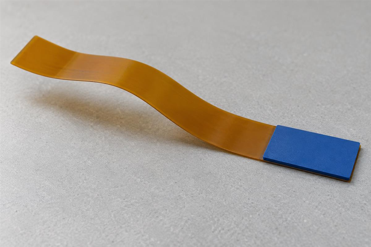
Choose the fewest layers and the support arrangement that satisfy the electrical and mechanical requirements together. More layers provide routing options, but they do not automatically provide a better moving interconnect.
- Single-conductor-layer flex: consider it when connections can be routed in one layer. Check whether the required shielding, return paths and contact arrangement can also be achieved.
- Double-sided or multilayer flex: consider it when routing or electrical requirements need additional conductors. Review how the complete stack behaves in the intended bend areas.
- Flex with local stiffeners: consider it when only selected termination or component areas need support. Verify the supported area’s dimensions and how forces enter the adjacent flex.
- Rigid-flex: consider it when integrated rigid circuit sections and flexible connections solve the assembly problem. Compare the complete assembly, including serviceability and replacement, with separate boards and interconnects.
Do not choose rigid-flex simply because the product contains a connector. Conversely, do not assume that adding a stiffener creates the same electrical structure as a rigid-flex board. Ask for a cross-sectional stack drawing and identify which layers carry conductors in each region.
Material and construction terminology can be confusing in a quotation. Our copper clad laminate specification guide explains why a laminate description and a finished-board requirement are not interchangeable.
Recognize Where Flex Helps and Where It Adds Risk
Flex is useful when its geometry solves a real packaging or interconnection problem. It also introduces handling and mechanical requirements that a rigid board may not have. Compare complete solutions, not just the price of one bare circuit.
In a hypothetical compact sensor, a flexible tail might connect two surfaces that are not coplanar. The useful benefit is a defined connection path within the enclosure. The corresponding check is whether assembly leaves sufficient clearance and avoids trapping the tail against an edge.
In a serviceable instrument, separate rigid boards and a removable interconnect may make replacement easier. An integrated structure could remove some connections but increase the scope of a repair. Neither option wins automatically; document which parts must be replaceable.
In a moving mechanism, a flex circuit may provide an organized signal path through limited space. The corresponding risk is that a poorly constrained path concentrates motion at one location. Validate the actual mounting and movement rather than testing an unconstrained strip that does not represent the product.
Electrical performance also needs its own review. A flexible substrate does not inherently guarantee lower loss, better impedance control or a higher voltage rating. State the signal, current, insulation and environmental requirements, then evaluate the proposed construction against them. Do not carry a generic material table into a product specification without confirming its test conditions.
Define the Bend Before Approving the Circuit
A bend requirement must describe geometry and use. “Must be flexible” leaves the supplier unable to judge whether the proposed stack is suitable. Mark the bend zones on a drawing and show the installed arrangement.
- Show the shape: provide the flat outline and the installed geometry, with mounting points and nearby obstructions.
- Define the movement: record whether the shape is fixed or changes, its travel and the expected number of operations.
- Identify the tightest bend: state the radius definition and tolerance. Do not confuse radius with diameter or measure only the outside envelope.
- Identify the local stack: use the thickness of the relevant flexible region, including its specified layers, not the thickness of a nearby stiffener.
- Describe exposure: include operating temperature, moisture, chemicals and any assembly or storage constraints.
- Agree on evidence: have the supplier review the geometry and propose the tests needed for the intended use.
A numerical example shows why definitions matter. Suppose a drawing calls for a 4 mm forming diameter. That describes a 2 mm radius, not a 4 mm radius. If a review worksheet uses radius divided by flex thickness, the two interpretations produce a twofold difference. This is a geometry example, not a recommended bend size or a life prediction.
Do not select one online thickness multiplier and use it for every layer count and duty cycle. Obtain a construction-specific review. Likewise, distinguish a material’s short thermal exposure during processing from its allowable operating conditions in the complete assembly.
Before release, close any ambiguity about the start and end of a bend zone, termination support, assembly access and the permitted installation method. A correct flat drawing is necessary, but it cannot alone explain how the circuit will be handled and mounted.
Check a Prototype Against Its Intended Use
A useful prototype check asks whether the proposed circuit works in its intended assembly, not merely whether it looks flexible. Define the test plan before testing so that a convenient result does not become the acceptance criterion afterward.
| Check | What to record | What it does not prove alone |
|---|---|---|
| Identity and construction | Drawing revision, supplied stack and material documentation. | That appearance establishes the exact material grade. |
| Fit and installation | Mounting, contact engagement, clearance and the actual forming procedure. | Long-term motion life. |
| Electrical operation | Required connections and product-specific electrical measurements. | Reliability after future mechanical or environmental exposure. |
| Representative motion | Fixture, travel, bend geometry, cycle count, monitoring and observed failures. | Performance outside the tested construction and conditions. |
| Relevant environmental exposure | Agreed conditions, sample identification and before/after checks. | Universal suitability for every temperature or chemical. |
Use the same mounting constraints that the product imposes. Inspect after installation, verify the required electrical behavior, and then carry out the agreed mechanical and environmental checks. For motion testing, determine whether continuity must be monitored during movement; a measurement only after the test may not reveal an intermittent fault.
Document failures precisely. “The flex failed” is less useful than a record of where the interruption occurred, the motion state, the construction revision and the inspection evidence. Avoid repeatedly bending a suspect sample by hand before recording its condition, because that can introduce additional damage.
The practical handoff is a short review package: circuit data, stack drawing, installed geometry, duty profile, electrical requirements, environmental conditions and acceptance criteria. Add BOM and placement information when assembly is included. Confirm who owns each unresolved requirement before authorizing production.
Flexible PCB Questions
Is a flexible PCB different from a flex circuit?
The terms commonly describe the same general technology. Use a drawing and construction specification to remove ambiguity; a name alone does not define layers, materials or movement capability.
Can every flexible PCB bend repeatedly?
No. Some are designed to be formed during installation and then remain in place. Repeated motion requires a suitable construction, controlled geometry and validation for the intended duty.
Is a stiffened flex circuit the same as rigid-flex?
No. A stiffener provides local mechanical support. An integrated rigid-flex construction includes rigid circuit regions. Review the layer drawing rather than judging from the external shape.
Can components be mounted on a flexible circuit?
Yes, where the design and assembly process support them. Component mounting does not mean that the populated area should bend. Identify support, connection and moving regions separately.
What is the minimum bend radius?
There is no single value for every flex circuit. It depends on the construction and intended use. Define the geometry and duty, then obtain a supplier review rather than copying a universal multiplier.
How many bend cycles will it survive?
A meaningful answer needs a specified sample, construction, motion, environment and failure criterion. A cycle number without those conditions is not a product qualification.
Does polyimide make the whole assembly heatproof?
No. The complete construction and installed components have their own limits. A film property or brief process exposure cannot establish an unrestricted operating-temperature range.
What should I send before requesting a prototype?
Send the circuit files, proposed stack, flat and installed drawings, bend zones, expected motion, electrical requirements and test expectations. Identify any choices that still need engineering review.
To discuss the build, contact PCBtry with that package. Ask for confirmation of the proposed construction, manufacturing feasibility and the checks needed before release. Resolve open mechanical requirements before treating a quotation as an approved design.



1 Comment
Rigid-Flex PCB Manufacturing Process: Stackup, Lamination and Testing - thindry pcb manufacturer · 08/24/2026 at 15:22
[…] If you need a primer on flexible circuits before following the integrated process, read what flexible PCBs are. […]