




A PCBA tester is a system that connects to an assembled circuit board, applies defined conditions, measures its response and records a decision against an approved test specification. It may combine a fixture, instruments, switching, programming tools and software. The fixture alone is not the complete tester, and a green pass indicator is meaningful only when the test coverage and limits are known.
When specifying a tester, start with the faults and product functions you need to check. Then determine how the system will reach those signals, make trustworthy measurements and distinguish a bad board from a bad connection in the test station.
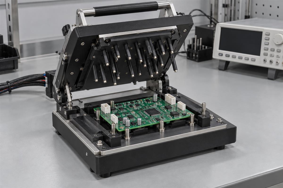
Start With the Board’s Test Requirements
Define the required decisions before choosing instruments or ordering a fixture. “Test every board” describes a production policy, not what the tester must establish.
For a controller board, the required decisions might include whether its supply rails meet their limits, whether programming completed correctly, and whether an input produces the expected output under a defined load. These are separate checks. Successful programming does not prove that the output driver works.
| System element | Purpose | Question before approval |
|---|---|---|
| Fixture and interface | Locate the board and connect the intended signals | Are contacts accessible and repeatable without damaging the assembly? |
| Stimulus and loads | Provide power, input signals and representative operating loads | Do the settings reproduce the approved test conditions? |
| Measurement instruments | Measure voltage, current, timing or other specified behavior | Are range, uncertainty and acquisition speed suitable? |
| Switching and wiring | Route signals between the board and equipment | Can routing errors, voltage drops or interference affect the decision? |
| Test software | Control the sequence, limits, errors and result logging | Can an incomplete test ever be recorded as a pass? |
| Safety controls | Manage the hazards of the actual product and station | Has a qualified engineer reviewed access, isolation and shutdown behavior? |
Give the test developer the board revision, schematic, relevant layout data, connector pinout, firmware requirements, operating modes, critical characteristics and expected production demand. Identify requirements that remain unresolved. A missing acceptance limit is an engineering question, not permission for the tester builder to invent one.
Use a coverage list that maps each required decision to a test step and its recorded evidence. Include known exclusions. For example, a room-temperature production test may screen assembly faults without demonstrating environmental endurance. Neither a tester purchase nor a passing batch automatically establishes product certification.
Choose the Test Approach Before Buying Hardware
Choose a test approach according to the faults, access and throughput requirements, then specify the equipment that can implement it. No single method provides universal coverage.
| Approach | Useful role | Equipment-planning constraint |
|---|---|---|
| In-circuit testing | Check selected assembly connections and component characteristics | Test access, circuit interactions, fixture design and the actual test program govern coverage |
| Flying-probe testing | Use movable probes for accessible electrical checks | Reachable features and test duration still matter; moving probes cannot reach every hidden node |
| Functional testing | Exercise specified board behavior under controlled inputs and loads | Requires product-specific procedures, firmware and measurable acceptance criteria |
| Programming with verification | Load and verify the specified software or configuration | Successful transfer is not a substitute for checking the functions affected by that software |
Optical and X-ray inspection contribute different evidence from electrical and functional tests. For a fuller comparison, use the circuit-card testing coverage guide. Keep the tester quotation focused on the combination actually required by your product.
For throughput, measure the entire station cycle: loading, identification, connection, test, data handling and unloading. A ten-second measurement sequence does not mean one board ships every ten seconds. Retests, fixture cleaning and maintenance also affect usable capacity. Request a demonstration with the intended handling process rather than relying only on instrument speed.
Likewise, compare lifetime support costs alongside the purchase price: replaceable contacts, spare cables, calibration, software maintenance, changeovers and access to the test source files. Clarify ownership and support responsibilities before the equipment arrives.
Design the Fixture as Part of the Measurement
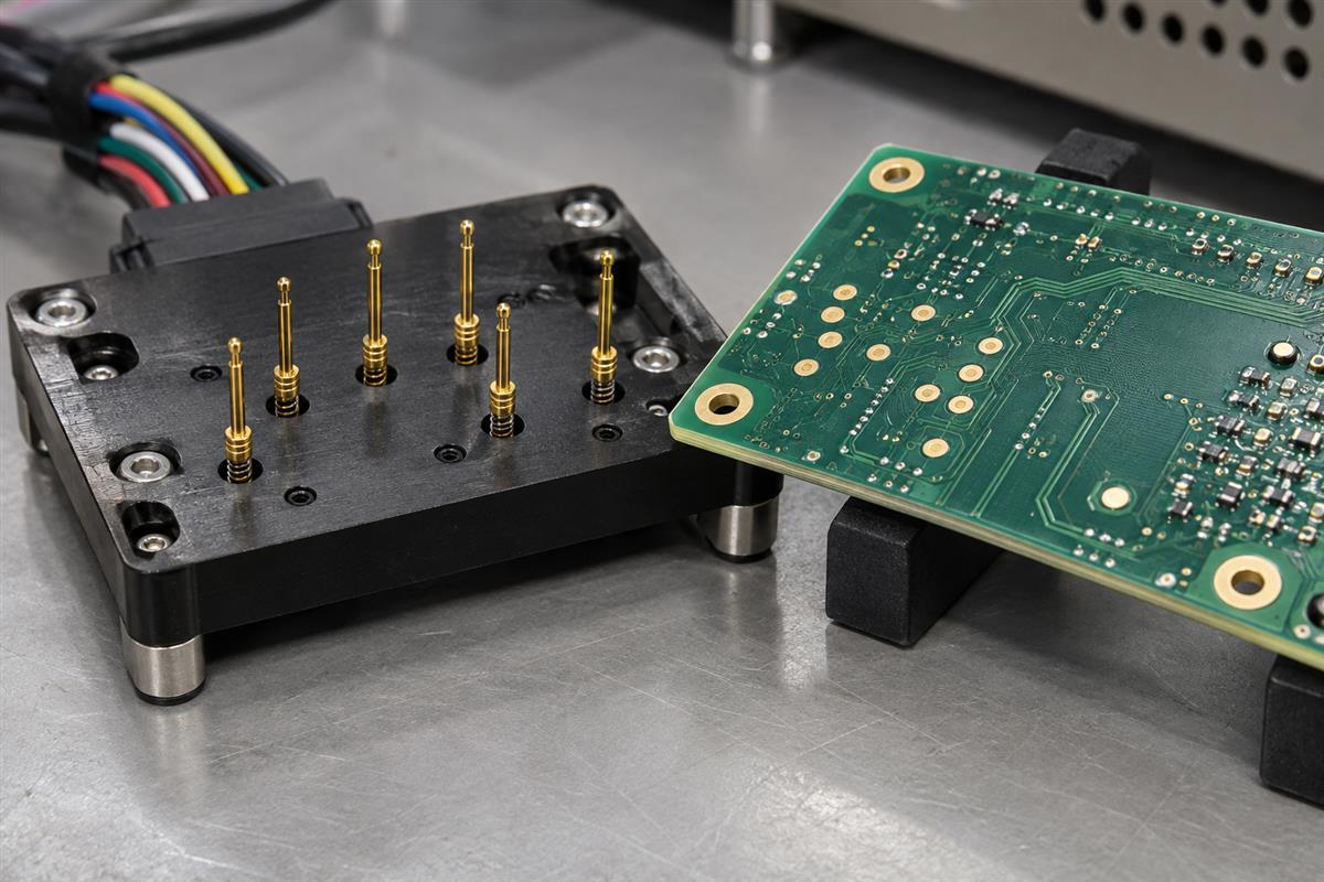
The fixture must make the intended electrical connection while holding the board consistently. A mechanically impressive fixture can still produce unreliable results if its contacts or wiring are wrong.
Spring-loaded contacts, often called pogo pins, touch designated conductive features when the fixture closes. Their location, working travel and required force must fit the board and chosen probe specification. Do not select these from a generic pitch or force rule without reviewing the actual assembly.
Check component clearance on both sides, locating features, board support and access for maintenance. Review accumulated contact force and unsupported board areas with the fixture designer; pressure sufficient to make contact should not be assumed harmless to a thin or densely populated assembly.
Electrical review should include the complete path from the instrument terminal to the board and back. Connector resistance, relay contacts and cable resistance can influence a measurement. Sensitive, high-current and high-frequency paths have different routing needs; an ordinary continuity check cannot qualify all of them.
Keysight’s ICT fixture verification guidance addresses the fixture itself, including missing probes, incorrect wiring, unintended shorts and open connections. That is a useful procurement distinction: the supplier should demonstrate the interface, not merely show that one board can produce a pass.
- Match every required contact to the approved net or connector pin.
- Identify inaccessible or unreliable contact locations before tooling release.
- Document replaceable probe and cable parts and the inspection procedure.
- Define how the station detects an absent or incorrectly seated board.
- Review shielding, grounding and measurement references for the intended signals.
- Specify safe connection, power removal and access behavior with qualified personnel.
High voltage, large stored energy, batteries and exposed moving mechanisms require a product-specific safety design. Do not use this checklist as an instruction to build or defeat protective controls.
Set Limits for a Defined Operating State
A measurement limit is incomplete unless the test also defines where, when and under what conditions the measurement is made. The same healthy board can produce different readings in startup, idle and active modes.
For each numerical check, specify the measured quantity, connection and reference, units, board state, stimulus, load, settling or acquisition conditions, limits and the response to an invalid measurement. For communication checks, define the expected transaction and timeout behavior instead of treating any received byte as success.
FixturFab’s test-specification guidance emphasizes defined measurement points and conditions. It also distinguishes a prototype’s measured result from justified production limits. Use the approved design requirements and measurement assessment, not the most convenient number observed on one sample.
A contact-drop example
Suppose, solely as a teaching example, that a fixture’s supply-and-return path has a combined resistance of 0.20 ohm and the board draws 0.50 A. The path drop is:
Voltage drop = current × resistance = 0.50 A × 0.20 ohm = 0.10 V.
A source set to 5.00 V could therefore deliver about 4.90 V at the board under these simplified steady-state assumptions. This does not prove a regulator fault. It shows why the test must define the measurement location and account for the fixture path. The numbers are hypothetical, not recommended operating settings or acceptable contact resistance.
Instrument display resolution is also not the same as measurement accuracy. Include relevant instrument, connection and environmental contributions when assessing uncertainty. If a result lies close enough to a product limit that uncertainty affects the decision, apply the engineering-approved decision rule; do not silently widen the limit to improve yield.
Some checks need both upper and lower bounds, while others need a different condition entirely. A low current can indicate a desired standby state or a circuit that never started. Tie the decision to the commanded state and an independent indication that the intended function actually ran.
Separate Board Failures From Station Problems
Preserve the first failure and investigate whether it follows the board, the contact path, the configuration or the station. Repeatedly testing until a pass appears destroys useful evidence.
| Observed symptom | Possible explanation, not a diagnosis | Evidence to gather |
|---|---|---|
| Result changes after reseating | Contact instability, board flex, connector seating or an intermittent assembly fault | First and subsequent readings, seating condition and the affected contact path |
| Many boards fail the same channel suddenly | Station or configuration fault, or a shared production defect | Station self-check, controlled reference results, change history and lot identity |
| Only one station reports failures | Instrument settings, wiring, calibration or software differ | Matched test revisions and a controlled cross-station comparison |
| Failures occur immediately after a software change | Sequence, timing, limit or reporting behavior changed | Version comparison and replay of approved validation cases |
| Average value passes but the product resets | A transient or operating mode may be missing from the measurement | Appropriate time-resolved measurements under the specified conditions |
Begin by recording the board identifier, station, fixture, software revision, failing step, raw result and error message. Quarantine unresolved units according to the production procedure. Check the station with suitable controlled references, then isolate one variable at a time where practical.
A known-good reference board is useful, but it is not an infallible standard. It can age, become damaged or fail to exercise a particular measurement path. Keep its identity, configuration and verification status controlled, and use independent measurement references when appropriate.
If a retest is allowed, define the reason, maximum attempts and final disposition rule in advance. Keep the original failure linked to the later result. An operator should not need to disconnect a cable repeatedly or alter a limit to obtain a shippable record.
Accept and Maintain the Tester With Evidence
Accept the tester only when it demonstrates the intended decisions and produces traceable records. Showing a good board pass is necessary in many plans, but insufficient to show that the station rejects the faults it was built to find.
NI’s test-system verification and validation guidance separates implementing the specified test correctly from proving that the test serves its intended purpose. It also calls for reviewing the impact of changes. Apply those principles to your approved acceptance plan rather than treating installation as acceptance.
- Review coverage. Link requirements to executed tests and identify exclusions or unsupported cases.
- Verify the measurement chain. Confirm instrument configuration, fixture mapping and appropriate references using the approved procedure.
- Challenge the decisions. Use safely prepared, authorized validation cases or simulations that represent relevant faults and boundary conditions. Do not create hazardous faults on live equipment.
- Check repeatability. Evaluate the agreed boards and conditions across repeated loading, operators or stations as relevant. Set sample sizes and acceptance criteria through the project’s engineering plan, not an arbitrary universal count.
- Exercise abnormal outcomes. Confirm that communication loss, interrupted testing, missing data and unexpected instrument errors cannot become ordinary passes.
- Approve the release package. Retain versions, configuration, validation results, known limitations, operating instructions and responsible approvers.
A production record should identify the board and revision, tester and fixture, software and limit-set revision, timestamp, individual results with units, overall disposition, and any linked retest or repair history. Preserve actual measurements where useful; a final pass/fail label alone makes trend analysis and later investigation difficult.
Plan maintenance according to the equipment supplier’s instructions and actual use. Review results after replacing probes, cables or instruments, changing firmware, modifying the fixture or updating limits. Revalidate the affected functions before production release. Coordinate software and security updates through controlled change management rather than leaving the station permanently unpatched.
PCBA Tester Questions
Is a test fixture the same as a PCBA tester?
No. The fixture holds and connects the board. The complete tester also needs the means to apply conditions, measure responses, make decisions and record results. Some fixtures contain electronics, but that does not remove the need to define and validate the complete system.
Can one tester support several board revisions?
Possibly, if the mechanical interface, connections and test configuration support them. Use explicit revision identification and approved configuration selection. A board that physically fits should not automatically receive another revision’s limits or programming file.
Can I specify functional testing with Gerber files alone?
No. Fabrication data does not fully describe expected behavior. Provide the schematic, interfaces, firmware information, operating states, stimulus and load requirements, and measurable acceptance criteria. Clarify which missing requirements must be developed before the test system can be quoted.
Does a calibration certificate prove the whole station is correct?
No. Instrument calibration is one part of measurement confidence. Wiring, switching, fixture contacts, software settings and the board connection also affect the result. Check the complete measurement path and the scope and status of relevant calibration records.
Is a higher pass rate always an improvement?
No. It may reflect a process improvement, but it can also result from missed tests, wider limits or changed retry behavior. Review test revisions, failure distributions and validation evidence before interpreting a yield increase as better product quality.
Should every fault be injected into an actual board?
No. Select safe validation methods with the test engineer. Controlled samples, independent references and simulations may address different requirements. Document what each method demonstrates and what it cannot represent; never improvise dangerous faults to prove a tester works.
Who should own the test limits?
The responsible product and test engineering teams should approve the limits and their rationale, with quality involvement as appropriate. Procurement can request evidence, but price pressure or an operator’s desire to clear failures should not determine electrical acceptance limits.
What should be included in a tester quotation?
Request separate scope for requirements development, fixture hardware, instruments, software, validation, documentation, training, spares and ongoing support. Identify customer-supplied items and exclusions. Agree who owns the files and who approves changes before comparing totals.
Preparing a PCBA build with a defined test scope? Review the PCB assembly service and send PCBtry your board revision, schematic, interface details, quantity and test requirements. Ask which tests, fixtures and records can be supported for the project, and resolve the uncovered requirements before production.



0 Comments