




An aluminum PCB prototype should demonstrate that a specified board can be manufactured, assembled and cooled in its intended installation. A sample that lights up on a workbench has not necessarily passed the electrical-isolation, mechanical-fit or thermal checks needed for production.
When choosing an aluminum PCB manufacturer, agree on the material stackup and acceptance evidence before comparing prices. This guide focuses on conventional insulated metal substrates: copper circuitry separated from an aluminum base by an electrically insulating, thermally conductive dielectric. Specialized direct-thermal-path constructions need a separate design review.
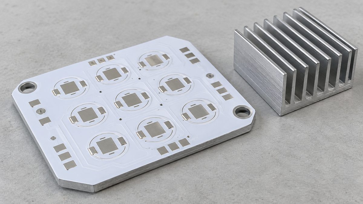
What should an aluminum PCB prototype prove?
Define the decision the prototype must support. A mechanical sample, an electrically tested bare board and a fully assembled thermal-validation unit answer different questions. Ordering one does not automatically provide the evidence of the others.
| Prototype purpose | What you need | What it does not prove |
|---|---|---|
| Check enclosure and heat-sink fit | Correct outline, hole positions, thickness and mounting surfaces | Operating temperature or electrical isolation |
| Check bare-board manufacture | Approved stackup, dimensional inspection, net testing and agreed isolation checks | LED junction temperature or completed assembly function |
| Check assembly | Actual components, soldering process, inspection and functional test | Performance in a different enclosure or ambient condition |
| Approve thermal performance | Representative assembly, heat sink, interface material, mounting and controlled test conditions | Every future operating condition or long-term reliability |
For example, a lighting developer may first need ten assembled boards for a fixture test. The order should state whether the supplier provides only the aluminum circuit boards, the populated boards, or the boards plus thermal interface and heat sink. Otherwise, two quotations with the same quantity may describe very different deliveries.
Keep the prototype configuration close to the intended product. An oversized laboratory heat sink can hide a thermal limitation that appears later in the production enclosure.
Which stackup details must be fixed before a quote?
Specify the copper, dielectric and aluminum separately. “Aluminum PCB, 1.6 mm” is not a complete stackup: it leaves the insulating material, copper condition and meaning of the thickness unclear.
The copper forms the electrical circuit. The dielectric keeps that circuit electrically isolated from the metal while allowing heat to pass through. The aluminum spreads heat and supports the assembly. Heat still needs a route from the board into its mounting structure and surrounding environment.
- Circuit: copper-layer count, required finished copper, line/space rules and surface finish.
- Dielectric: manufacturer and grade, thickness, thermal-property test method, and the electrical and temperature requirements it must satisfy.
- Metal base: alloy where relevant, metal thickness, and required surface condition.
- Mechanical drawing: finished board thickness and tolerance, outline, slots, hole sizes, countersinks if applicable, and contact-surface requirements.
- Electrical boundary: which conductors must be isolated from the base, whether the base is deliberately bonded to chassis, and applicable product requirements.
Ask for a drawing showing whether “board thickness” means the complete finished construction or only the metal base. Also identify plated electrical holes separately from mechanical mounting holes. An electrical connection passing through conductive metal needs an engineered isolation structure; it is not equivalent to drilling a hole through ordinary FR-4.
Do not remove the dielectric or drill an improvised thermal connection to the aluminum base. That can defeat the intended isolation. A manufacturer may offer a purpose-designed direct-thermal-path structure, but its exposed thermal pad and electrical potential must be compatible with the component and product. Treat it as a different construction, not a shortcut.
For a separate explanation of how these constructions are fabricated, see the aluminum PCB manufacturing process. Here, the purchasing objective is an approved stackup that both parties can identify and reproduce.
Does a higher W/mK rating guarantee a cooler board?
No. Thermal conductivity describes a material; operating temperature depends on the complete heat path. Dielectric thickness, effective heat-transfer area, component attachment, spreading and heat-sink contact all matter.
A simple calculation illustrates the distinction. For one-dimensional conduction through a uniform layer, thermal resistance is approximately R = t / (k × A), where t is thickness in metres, k is thermal conductivity in W/(m·K), and A is area in square metres. The result is K/W, numerically equivalent to °C/W for a temperature difference.
| Hypothetical dielectric | Thickness t | Conductivity k | Assumed area A | Calculated layer resistance |
|---|---|---|---|---|
| A | 100 µm = 0.000100 m | 2 W/(m·K) | 100 mm² = 0.000100 m² | 0.50 K/W |
| B | 200 µm = 0.000200 m | 3 W/(m·K) | 100 mm² = 0.000100 m² | 0.67 K/W |
Material B has the higher conductivity, but doubling its thickness more than offsets that advantage in this simplified example. With 5 W flowing through the assumed area, the calculated drop across this layer alone is about 2.5°C for A and 3.3°C for B.
These are teaching values, not supplier specifications or predicted component temperatures. Real heat spreading is three-dimensional, the effective area may differ from a component’s footprint, and interfaces add resistance. Do not use this calculation to reduce insulation thickness without checking electrical requirements.
Henkel’s Thermal Clad selection guide discusses dielectric thickness, thermal impedance and interface effects. Request comparable measurements for the proposed grade and thickness, not just the largest conductivity number in a brochure.
How do you compare aluminum PCB prototype quotes?
Compare the same construction, delivery scope and acceptance requirements. Price differences are meaningful only after those conditions match.
| Quote line to align | Question to send the supplier | Why it changes the comparison |
|---|---|---|
| Laminate | What exact dielectric grade and thickness are included? Are substitutions permitted? | Different grades can change thermal, electrical and processing behavior. |
| Board construction | Are copper, base thickness, finished thickness and tolerances identical? | A similar-looking board may not be mechanically or electrically equivalent. |
| Machining and panel format | Are slots, countersinks, deburring, scoring and assembly rails included? | Individual boards and assembly panels create different work and costs. |
| Testing | Which bare-board and assembly tests are included, under what conditions? | “Tested” may mean continuity only. |
| Assembly | Does the price include components, stencil, assembly, inspection and functional test? | A bare-board quote is not an assembled-prototype quote. |
| Delivery | When does lead time start, and are freight, tooling and setup separate? | Material approval and engineering questions can precede fabrication. |
| Production transfer | Will production use the approved prototype material and construction? | A substitute sample may validate the wrong build. |
Send Gerber or another agreed fabrication data format, drill data, a dimensioned drawing, the stackup request, quantity and delivery destination. Add a BOM with manufacturer part numbers, placement data and assembly instructions if components are included. Provide your thermal and isolation requirements rather than expecting the board shop to infer them from copper artwork.
A manufacturer should be able to identify open engineering questions before accepting the job. Ask who approves substitutions, which process steps are performed by partners, and what inspection records accompany the samples. A certificate or factory photograph alone does not answer those build-specific questions.
What should you check when the prototype arrives?
Inspect the physical board and match its records to the approved revision before applying power. Start with checks that can reveal an incorrect build without damaging it.
- Confirm identity. Match part number, revision, quantity and material documentation to the purchase order. Resolve undocumented changes before validation.
- Check fit. Inspect outline, mounting holes, slots, thickness and the intended heat-sink contact face against the drawing.
- Inspect edges and holes. Look for burrs, damaged insulation, metal debris and unintended contact between copper and exposed metal. Photograph suspect areas for the supplier.
- Review board test evidence. Distinguish circuit continuity/short testing from isolation testing between circuitry and the metal base.
- Release for controlled assembly or system testing. Use the agreed assembly process and inspection criteria, then run the functional and thermal plan.
A multimeter can reveal some gross shorts; it cannot certify dielectric withstand or long-term insulation reliability. High-voltage isolation testing belongs with qualified personnel, appropriate guarded equipment and an approved procedure. Test voltage, waveform, ramp, duration and acceptance limit must come from the applicable requirements and approved construction, not from a generic blog value.
The Thermal Clad guide also explains that IMS capacitance affects test current, so an initial charging response must not automatically be called insulation leakage. This is another reason to request the actual test setup and result rather than a bare “hipot passed” statement.
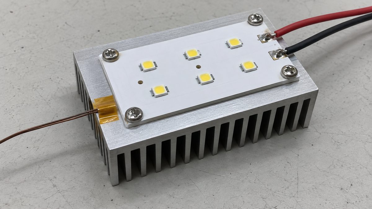
How do you run a useful thermal comparison?
Change the board variable you want to compare and hold the surrounding conditions constant. Otherwise, a lower measured temperature may come from a different heat sink, airflow or mounting pressure rather than the substrate.
- Write the test conditions first. Record ambient temperature, airflow, enclosure, orientation, heat sink, interface material and mounting method.
- Define the electrical load. Use the same operating mode and record input conditions. Electrical input power is not always equal to heat generated; LEDs also emit optical power.
- Use repeatable measurement points. Identify component, board and heat-sink locations. A surface temperature is not automatically semiconductor junction temperature.
- Wait for the agreed stability criterion. Record temperature against time. Define the allowable change over an observation interval before testing, rather than choosing a convenient time afterward.
- Compare results with limits and uncertainty. Use component and product requirements, allow for sensor accuracy, and repeat questionable measurements. Stop if temperatures exceed approved limits or the assembly shows abnormal behavior.
For example, testing sample A with thermal paste and sample B with a dry, uneven mounting face is not a clean laminate comparison. First match the mounting interface. Photograph the arrangement and record the installation procedure so another engineer can reproduce it.
If using an infrared camera, account for emissivity and reflections: a shiny aluminum surface can produce misleading readings. Use a validated measurement method and appropriate reference measurement. Do not interpret an attractive thermal image as proof of a passing product.
The result should state what was tested and under which conditions. “Passed at the specified load and ambient in enclosure revision C” is useful. “Excellent heat dissipation” is not a test result.
What must remain unchanged for production approval?
Approve the documented build, not merely the sample’s appearance. A production change can invalidate part of the prototype evidence even when the outline and solder-mask color remain identical.
Save this release checklist with the approved files:
- Board artwork, drill files and mechanical drawing share the approved revision.
- Dielectric manufacturer, grade and thickness match the validated construction, or an approved change assessment exists.
- Copper, base thickness, finish, tolerances and mounting surfaces are controlled.
- Hole isolation and edge requirements remain consistent with the electrical design.
- Components, assembly process and inspection requirements are identified.
- Heat sink, interface material, mounting method and enclosure match the thermal-validation configuration.
- Test procedures, acceptance criteria and required records are agreed.
- The supplier knows which changes require notification and written approval.
A small sample run demonstrates only the units and conditions tested. It does not establish production yield or lifetime reliability. Agree on any additional qualification, first-production inspection or lot sampling required by the application.
Use PCBtry’s metal-core PCB service page for the manufacturing discussion. A prototype review should resolve the actual stackup and acceptance questions before a larger order is committed.
Aluminum PCB prototype questions
Is an aluminum PCB the same as a metal-core PCB?
An aluminum-based board is one type of metal-core or metal-backed construction. The broader category also includes other metals and different stackups. Identify the actual cross-section rather than treating every MCPCB as interchangeable.
Can an FR-4 prototype validate an aluminum production board?
It may help check part of the circuit, but it does not validate the aluminum board’s thermal path, isolation structure or mechanical interface. State which early conclusions can carry over and repeat the construction-dependent tests.
Does the aluminum base count as a circuit layer?
Not automatically. A conventional single-circuit-layer IMS has patterned copper on one side of the dielectric and a supporting metal base. Describe electrical copper layers and the metal base separately when requesting a quote.
Should the aluminum base be grounded?
That depends on the circuit, enclosure and safety design. Do not let a mounting screw make an unintended electrical connection. Define bonding or isolation requirements on the drawing and verify them for the assembled product.
Will a thicker aluminum base always reduce temperature?
No. It can affect spreading, stiffness and contact, but another part of the heat path may dominate. Evaluate the complete construction and mounting conditions instead of selecting base thickness from total wattage alone.
Which surface finish should the prototype use?
Choose a finish compatible with the component geometry, assembly process, storage and product requirements. Prefer the intended production finish when assembly behavior is part of the trial. There is no universally best finish for every aluminum PCB.
How many prototypes should be ordered?
Count the units needed for assembly setup, functional tests, thermal comparisons, any destructive checks and retained references. A single working sample rarely covers all of those purposes. Qualification sample size should follow the applicable plan.
What if the quoted material is unavailable?
Request the proposed substitute’s grade, thickness and relevant data before approval. Review thermal, electrical, mechanical and processing differences, then decide which tests must be repeated. A matching conductivity number alone is not proof of equivalence.
Preparing an aluminum PCB prototype? Send your fabrication files, stackup request, quantity, mechanical drawing and test expectations through PCBtry’s contact page or email sales@pcbtry.com. Include the BOM and placement files for assembly. Ask for a written list of material assumptions, open engineering questions and included tests before approving the build.



0 Comments