
5G PCB design imposes significantly higher requirements compared to standard circuit boards. These boards transmit and receive high-frequency signals, making them susceptible to attenuation and interference. Furthermore, they generate more heat, among other challenges. This article explores the demands and design rules for 5G.
What is a 5G PCB?
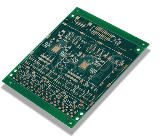
A 5G Printed Circuit Board (PCB) refers to a circuit board specifically designed, manufactured, and tested to support and enable fifth-generation (5G) mobile communication technology.
It does not represent an entirely new category of PCB but is a collective term for circuit boards that demand extremely high standards in materials, design, manufacturing processes, and reliability—far exceeding those of traditional PCBs, especially those used in 4G and earlier technologies.
In simple terms, a 5G PCB is a “super PCB” capable of meeting the challenges of high frequency, high speed, high density, and high reliability posed by 5G technology.
Why Does 5G Require Special PCBs?
The key characteristics of 5G technology are high speed, low latency, and massive connectivity. These features present unprecedented challenges for the PCB, which serves as the “foundation” carrying all electronic components:
- High Frequency (Millimeter Wave)
- Challenge: 5G utilizes higher frequency bands, particularly millimeter-wave (mmWave) bands (e.g., 28GHz). As frequency increases, signal loss during transmission becomes more significant.
- PCB Requirement: The substrate materials of traditional PCBs (like standard FR-4) exhibit very high loss at high frequencies, akin to a “bumpy mountain path” where signals attenuate quickly. Therefore, 5G PCBs must use special high-frequency materials with low-loss (Low Loss) or very low-loss (Very Low Loss) properties, such as hydrocarbons, Polytetrafluoroethylene (PTFE), or Liquid Crystal Polymer (LCP). This is equivalent to upgrading the “mountain path” to a “smooth highway.”
- High Speed
- Challenge: 5G’s data transfer rates are extremely fast, meaning the PCB carries very high-frequency digital signals.
- PCB Requirement: High-speed signals demand extremely stringent impedance control. The width, thickness of PCB traces, and their spacing from reference planes (ground or power planes) must be precisely designed and controlled to ensure stable impedance (e.g., 50 ohms). Any deviation can cause signal reflection and distortion, severely impacting system performance.
- High-Density Integration
- Challenge: 5G devices (e.g., base station AAUs and smartphones) incorporate increasingly complex functionalities while requiring smaller form factors. This necessitates integrating more components and denser trace routing on the PCB.
- PCB Requirement: 5G PCBs commonly employ advanced High-Density Interconnect (HDI) technology. This involves more micro-vias, buried vias, finer trace widths and spacing, and more complex layer stack-ups (e.g., 8, 12 layers, or more) to interconnect all functionalities within a limited space.
- Stringent Thermal Management Requirements
- Challenge: 5G chips and power amplifier devices consume more power and generate increased heat. If this heat is not dissipated promptly, it can lead to device throttling or even failure.
- PCB Requirement: 5G PCBs need excellent thermal dissipation capabilities. This is typically achieved by using PCB materials with high thermal conductivity, embedding metal cores or thermal coins in the design, and utilizing more advanced via technologies to aid heat transfer.
- High Reliability
- Challenge: 5G infrastructure, such as base stations, requires 24/7 operation under various harsh environmental conditions, demanding exceptional longevity and stability.
- PCB Requirement: Every step—from material selection and manufacturing processes to final testing—must meet higher reliability standards to ensure stable PCB performance over its operational lifetime.
5G PCB Design
The creation of a 5G PCB begins with the design phase, where engineers make critical decisions. Their choices determine how well the board will perform in high-frequency applications.
A significant challenge for fifth-generation PCBs is circuit miniaturization and strict tolerances. This necessitates engineers to implement advanced design considerations and tools.
A poorly designed board is more prone to failure, especially in harsh environments. Therefore, designers must possess the necessary expertise to ensure the board functions efficiently.
5G PCB Design Requirements
The requirements for 5G circuit boards primarily revolve around their high-frequency and high-data-rate applications. Let’s examine these requirements and how they influence the design process for manufacturing and assembly.
- High-Frequency Signal Transmission: The board must support high-frequency signal reception and transmission. Specifically, high-frequency signals have greater difficulty propagating around obstacles. They also generate heat within the substrate and components, potentially leading to board failure.
- High Data Rate and Bandwidth: The board design must support high data traffic and transfer rates. This requirement demands that designers ensure higher signal integrity. Furthermore, it requires them to carefully select and position transmission components. The board also houses components supporting high-frequency bands, increasing the number of devices it can connect to wirelessly.
- Low Signal Loss and Latency: Minimizing signal loss and latency is a primary requirement for 5G PCB technology. The board handles vast amounts of data per second. Consequently, it must deliver significantly lower latency (as low as 1 millisecond) compared to traditional printed circuit boards.
- High Thermal Performance: High-frequency circuits and components in 5G PCBs generate significant heat. They often also feature higher component density, increasing the risk of overheating. Therefore, their design must incorporate robust power and thermal management strategies.
5G PCB Design Principles
The 5G circuit board design process adheres to several key rules. These include selecting appropriate materials, optimizing layer stack-up, and ensuring proper routing and layout. Designers must also implement stringent EMI and thermal control measures.
- Material Selection: Suitable PCB materials must be chosen from the various available types. The material must dissipate heat rapidly and possess properties like low dielectric loss, which become more critical at higher frequencies. This translates to requirements for high thermal conductivity, low Dielectric Constant (Dk), and low Dissipation Factor (Df). Various materials fit this description, including substrates from Rogers and Isola. Additionally, there are flexible 5G PCB materials like Teflon.
- Layer Stack-up Configuration: The stack-up thickness must ensure the board operates reliably within the final 5G product or system. A board that is too thick or too thin can lead to signal quality issues. Industry standards recommend a thickness between ¼ and ⅛ of the application’s shortest wavelength. Other rules include proper separation of signal, power, and ground layers.
- Routing and Layout: Given that these PCBs generate and receive high-frequency signals, various routing rules must be followed during design. These rules include ensuring controlled impedance for transmission lines and using appropriate trace geometry and dimensions. Keeping traces short, correctly spaced, and with smooth surfaces enhances signal quality; smooth traces also reduce resistive losses. Separating analog and digital circuits within wireless communication circuits is crucial to prevent harmful coupling between unrelated signals, thereby improving board performance.
- Thermal and EMI Management:
Thermal management and EMI management are critical. Various measures help designers prevent the board from overheating or suffering from extreme signal attenuation or complete loss. Understanding the placement of heat-generating and heat-dissipating components is key. Heat sinks are essential, especially in compact designs incorporating microprocessors and other heat-producing elements. Thermal vias and copper planes are also vital. EMI mitigation techniques include isolating and shielding components. Rational component placement helps reduce signal interference from external sources and assists designers in meeting Electromagnetic Compatibility (EMC) reduction standards.
Key Material Evolution for 5G PCBs
Materials are the cornerstone determining the performance ceiling of 5G PCBs, and their evolution directly drives technological progress.
The table below compares mainstream high-frequency, high-speed PCB materials for 5G and their characteristics:
| Material System | Representative Model/Type | Core Characteristics (Dk/Df) | Advantages | Challenges & Application Scenarios |
|---|---|---|---|---|
| PTFE-based Substrates | Rogers RO3003 series, Taconic TLY-5 | Dk ~2.55, Extremely low Df (0.0013) | Extremely low loss, suitable for millimeter-wave frequencies | High processing difficulty (requires high-temperature lamination), high cost (~3-5 times that of FR-4) |
| PPO/PPE-based Substrates | Panasonic Megtron series, ITEQ IT988GSE | Low Df (e.g., 0.002) | Excellent CAF resistance, balanced performance and processability | Mostly used in high-speed digital circuits, such as data center servers |
| Hydrocarbon Resin-based Substrates | Rogers RO4000 series, TUC TUC872SLK | Dk ~3.38, Df ~0.0027 | Good balance of performance and cost, suitable for high-layer count boards | Thermal conductivity can be improved via ceramic filling; widely applicable |
| Liquid Crystal Polymer | LCP Substrate | / | Suitable for flexible applications like 5G mobile phone antenna modules | Dk stability is significantly affected by temperature |
| Modified Epoxy Resin | Some domestic new materials | Df ~0.006 | Low-cost solution (cost can be ~60% lower than PTFE) | Performance meets some Sub-6GHz applications, promoting the localization of high-frequency materials |
Frontiers in Material Innovation:
- Organic-Inorganic Composite Materials: For example, compounding PTFE with aluminum nitride ceramics can maintain low loss while increasing thermal conductivity to 2.5 W/m·K, meeting the heat dissipation needs of high-power chips.
- Nano-modification Technology: By adding fillers such as nano-alumina particles, the dielectric loss factor of the base resin can be significantly reduced, and the thermal conductivity of the material can be improved.
Manufacturing and Quality Control for 5G PCBs
Advanced materials and designs ultimately need to be realized through precision manufacturing.
- Stringent Processing Requirements
- Laser Direct Imaging and Vacuum Etching: To meet finer line widths/spacing (e.g., below 50μm), LDI and high-precision vacuum etching equipment are essential to ensure vertical sidewalls and precise dimensions.
- Plasma Treatment: After drilling, using plasma cleaning effectively removes drill smear, ensuring the metallization quality of high-frequency microvia walls, which is crucial for high-reliability applications.
- Comprehensive Testing and Validation
- Non-Destructive Testing and 3D X-Ray: Utilizing equipment like AOI and X-Ray to detect internal defects such as lamination voids and hole copper cracking.
- RF Performance Testing: 5G antenna PCBs require rigorous impedance testing, insertion loss testing, and passive intermodulation testing to ensure their high-frequency performance meets design expectations. Inspection standards must adhere to strict quality specifications, such as the QS9000 standard, and defects are managed through classification (Critical Defect CR, Major Defect MA, Minor Defect MI).
Primary Application Areas for 5G PCBs
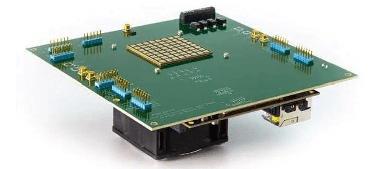
- Core Infrastructure:
- AAU (Active Antenna Unit): The core component of 5G base stations, responsible for signal transmission and reception. Contains numerous RF PCBs and digital PCBs.
- BBU (Baseband Unit): Handles data processing, dealing with extremely high-speed data streams, requiring the highest level of high-speed performance from the PCB.
- Terminal Devices:
- 5G Smartphones/CPEs: The mainboard and antenna modules inside phones are typical 5G PCBs, needing to integrate multiple mmWave antennas and process high-speed data.
- IoT Modules: Communication modules within various Industrial IoT (IIoT) and Vehicle-to-Everything (V2X) devices.
- Other Fields:
- Data Centers: The data deluge enabled by 5G requires higher-speed data centers. The servers, switches, and other equipment inside them also utilize high-speed PCB technology, which shares common requirements with 5G PCBs.
Summary
| Feature | Traditional PCB (e.g., 4G) | 5G PCB |
|---|---|---|
| Material | Standard FR-4, etc. | High-Frequency/High-Speed Materials (e.g., Rogers, Taconic) |
| Frequency | Lower (Sub-6GHz) | Very High (Millimeter Wave) |
| Signal Integrity | Standard Requirements | Extremely High Requirements, Precise Impedance Control |
| Integration Density | Standard HDI or Through-Hole | Advanced HDI, Any-Layer Interconnects |
| Thermal Management | Conventional Design | Active Cooling Design, Embedded Thermal Solutions |
| Manufacturing Cost | Relatively Low | Very High |
In conclusion, the 5G PCB is the physical cornerstone that enables 5G technology. Its technical sophistication directly determines the performance and reliability of 5G equipment, making it a crown jewel in the fields of electronic engineering and PCB manufacturing.


0 Comments