




A countersink is a cone-shaped recess for a screw with a tapered underside. A counterbore is a cylindrical recess with a flat seating shoulder, usually for a flat-underhead fastener such as a socket-head cap screw. Both can lower the screw head, but they are not interchangeable. On a PCB, the deciding question is whether the matching recess leaves enough material and clearance for a reliable mounting joint.
Start with the actual screw drawing, not just a label such as M3. Check its head shape, dimensions and angle against the PCB thickness, copper layers and support underneath. A hole can look correct from above yet cut into an internal plane or leave an inadequate load-bearing shoulder.
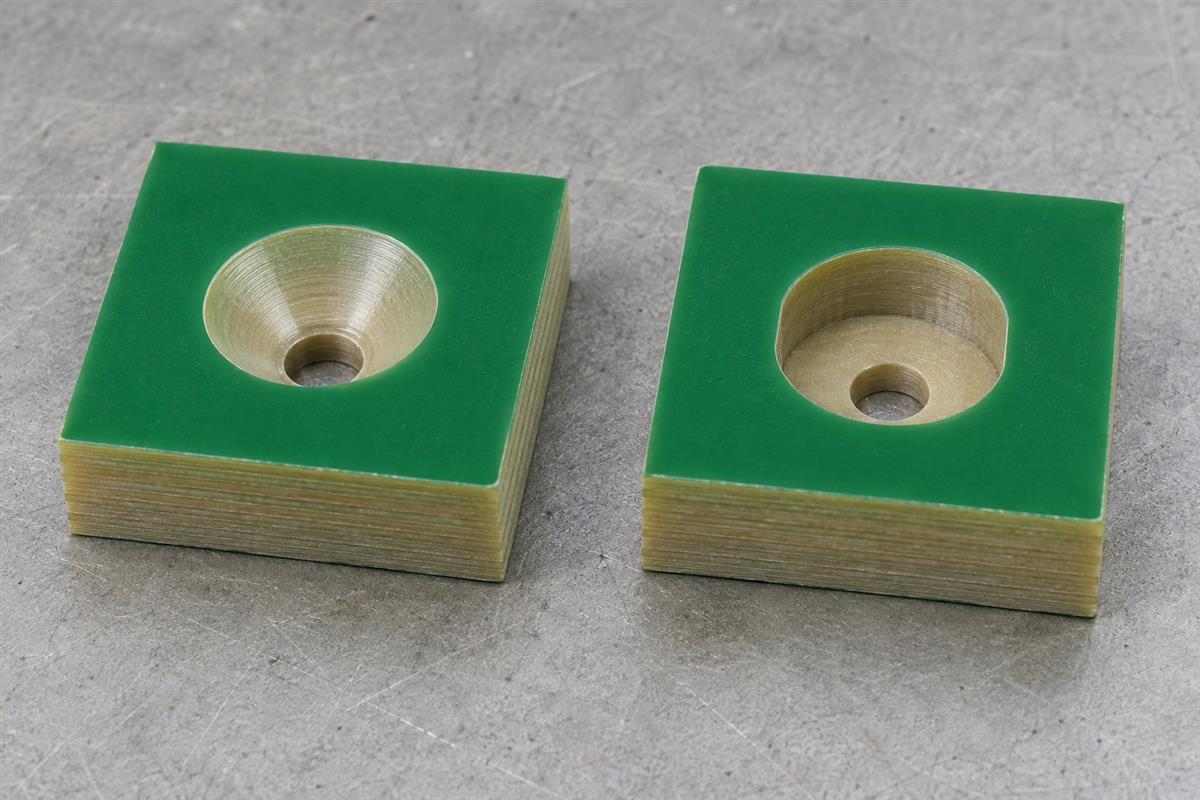
Match the Recess to the Screw Head, Not the Drive
Choose the recess from the surface underneath the screw head. The tool recess on top, such as a hex socket or Phillips drive, does not determine whether the PCB needs a countersink or counterbore.
| Decision | Countersink | Counterbore |
|---|---|---|
| What supports the head? | A tapered, cone-shaped seating surface | A flat annular shoulder around the smaller through hole |
| Matching head | A countersunk head with the specified included angle | A compatible flat-underhead screw, with room for its head and any specified washer |
| Geometry to control | Through-hole diameter, mouth diameter and included angle | Through-hole diameter, recess diameter and depth |
| First PCB concern | The cone may consume most of the local thickness | The recess may leave too little material beneath its shoulder |
| Do not assume | Every flat-head screw has the same angle | Every socket-head screw fits inside a thin board |
The PCBWay ordering guide distinguishes these two recess geometries. Neither shape is automatically stronger: the remaining laminate, contact area, support, fastener and assembly process determine whether the joint is suitable.
For a concrete angle reference, Accu lists its SSK-M3-5-A2 countersunk screw with a nominal 90-degree included angle. That is a specification for that part, not permission to choose 90 degrees for every screw. An angle mismatch changes where the head contacts the recess; tightening harder is not a correction.
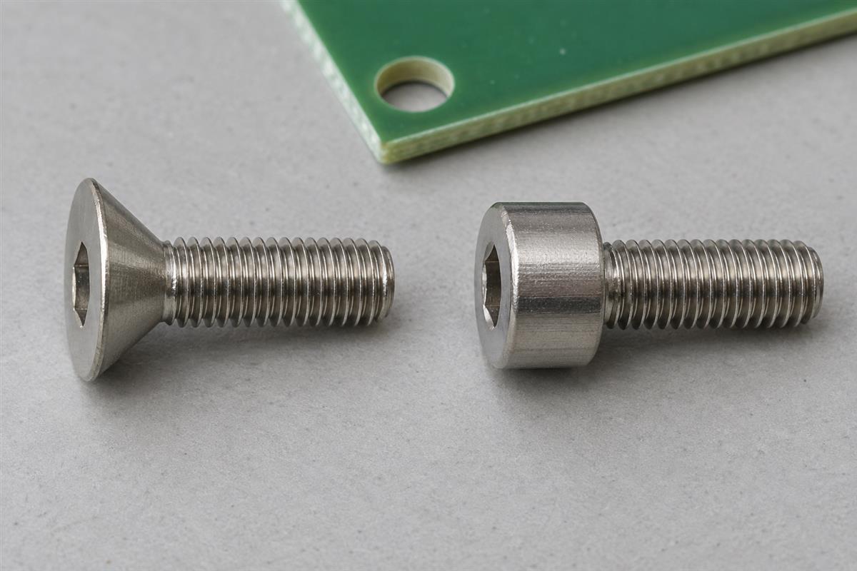
Also ask whether the head really needs to be flush. If there is clearance above the PCB, a normal through hole with suitable support may avoid unnecessary material removal. Recessing the head in an enclosure or bracket can be another option, provided the complete assembly is redesigned and checked.
Check Recess Depth Against the Available PCB Thickness
A recess is feasible only when its deepest permitted cut leaves a suitable board structure. Use the minimum permitted local board thickness and the maximum permitted recess depth, not just the nominal dimensions.
A countersink depth calculation you can check
For an ideal straight-sided cone meeting a cylindrical through hole:
h = (D – d) / [2 × tan(θ/2)]
- h: depth from the top reference surface to where the cone meets the smaller hole.
- D: countersink diameter at that reference surface.
- d: diameter of the smaller through hole.
- θ: the full included cone angle, not the angle of one side.
Use the same length unit for D and d. The formula follows from a right triangle: the radial increase is (D – d)/2, and its ratio to the depth is tan(θ/2). It is a geometry check, not a complete screw-seat design; real head tolerances, radii and the intended seating position still matter.
Illustrative example, not a recommended hole specification: let D = 6.0 mm, d = 3.2 mm and the board thickness be 1.6 mm. With a 90-degree cone, h = (6.0 – 3.2)/2 = 1.4 mm. Only 0.2 mm of axial thickness remains before the cone-to-hole transition reaches the underside. This small positive number does not demonstrate acceptable strength.
Keep the same diameters but change the angle to 82 degrees. The depth becomes approximately 1.61 mm, already greater than the nominal board thickness. The intended cone would break through the underside before reaching the specified smaller hole. This is why copying a mouth diameter while changing the screw angle can invalidate a design. Sierra Circuits also explains the relationship between countersink angle and depth.
Include the tolerances and the supporting material
For a simple one-sided depth check, minimum remaining thickness = minimum local board thickness – maximum recess depth. Both dimensions must use consistent reference surfaces. Agree whether the drawing controls the finished surface or the load-bearing laminate; solder mask is not a substitute for structural material.
For example, assume a drawing permits a minimum local thickness of 1.44 mm and a maximum recess depth of 1.45 mm. The difference is -0.01 mm: there is no guaranteed material remaining at the transition. These are deliberately chosen example limits, not a standard PCB tolerance. Set the actual limits with the fabricator; the separate PCB thickness tolerance guide explains what to clarify when specifying the board.
A counterbore has a simpler depth dimension but the same space problem. Accu’s SSCF-M3-30-A2 socket-head screw datasheet specifies a 3 mm head height. That head cannot be fully recessed within a 1.6 mm PCB while retaining a supporting shoulder. A different fastener, a thicker local structure or an external mounting arrangement is needed.
Do not approve a recess simply because the subtraction is positive. Ask the mechanical designer and fabricator to review the remaining material under the contact region, local reinforcement, support underneath, edge distance and expected loading. There is no single minimum residual thickness or tightening torque that this comparison can safely prescribe for every PCB.
Keep Machining and Hardware Away From Unintended Copper
Reserve space for both the material being removed and the installed hardware. A keepout based only on the small through-hole diameter can miss the larger screw head, washer, recess or tool envelope.
On the outer layers, check the maximum hardware footprint and its possible offset. On inner layers, check where the machined cone or cylinder intersects each copper plane. A top-view clearance around the pilot hole does not prove that a deeper cut misses internal copper. The KiCad PCB Editor documentation describes post-machining features and displays their intersections with copper layers; it also warns that not every fabricator supports these operations.
Separate two electrical intentions before routing:
- Isolated mounting: the hardware must not contact an unintended net. Define copper clearances through the full stackup, including the recess and hardware tolerances.
- Intentional bonding: identify the required net and contact surface, finish and inspection method. Do not assume that a plated hole or a screw touching a pad automatically provides the required electrical connection.
RS DesignSpark’s mounting-hole clearance guidance illustrates why the bolt head or washer, rather than just the hole, influences copper-pour exclusion. A visible solder-mask layer should not be treated as the only protection against an incorrectly placed metal fastener.
Ask the fabricator to confirm which surfaces are plated and when the recess is machined. Post-plating machining may remove an intended conductive surface; machining before plating requires a different process review. Keep these requirements separate from the fastener’s mechanical fit. For the wider support and enclosure arrangement, use the PCB enclosure mounting guide.
Put the Geometry and Acceptance Conditions on the Drawing
Give the fabricator an unambiguous recess definition and an agreed acceptance basis. A circular outline in Gerber data does not, by itself, communicate angle, depth, machining side or the required material left underneath.
| Drawing or order field | What to state | What ambiguity it removes |
|---|---|---|
| Feature location | Hole count and coordinates from identified datums | Which holes receive the special operation |
| Through hole | Finished diameter and tolerance; plated or non-plated requirement | Whether a nominal drill number describes the delivered hole |
| Countersink | Mouth diameter and included angle, with their tolerances | The intended tapered seating geometry |
| Counterbore | Recess diameter, depth and tolerances | The flat seating shoulder and its position |
| Side and datum | Top, bottom or both; depth reference surface | Mirror-image or wrong-side machining |
| Remaining material | Critical minimum, reference surfaces and approved stackup | Whether the mechanical constraint survives thickness variation |
| Electrical intention | Isolated or bonded mounting; copper keepout and surface-plating requirements | Unwanted plane exposure or loss of an intended contact |
| Hardware and inspection | Part number, seating requirement, sample checks and drawing revision | What the recess must actually fit and how acceptance is judged |
Do not independently tolerance every dependent countersink dimension without checking that the limits are compatible. If angle and diameters control the geometry, identify any calculated depth as reference information unless the drawing explicitly establishes how all requirements are to be satisfied.
Send the fabrication drawing together with copper and drill data, stackup and the relevant hardware drawing. Eurocircuits’ mechanical-layer guidance emphasizes communicating dimensions, tolerances and special build requirements. Keep the same revision across the files so the fabricator does not receive an old recess callout with a new board thickness.
Before authorizing production, request written confirmation of the supported geometry, achievable tolerance, copper clearance and any proposed change. Availability in CAD software is not manufacturing approval, and a standard PCB quotation may not include the special machining operation.
Inspect a Sample Before Releasing the Mounting Design
Approve the recess using dimensional evidence and a trial assembly with the specified hardware. A screw appearing flush is useful evidence of position, but not proof of correct angle, intact laminate or sufficient load capacity.
- Match the revision. Confirm that the sample board, mechanical drawing, stackup and fastener part number belong to the same design.
- Check the manufactured geometry. Verify hole size, recess size, depth or angle, machining side and the agreed remaining-material requirement using suitable measurement methods. Ask how critical internal features will be verified when they cannot be measured directly.
- Inspect the local area. Look for damaged fibers, cracks, loose debris or unintended exposed copper. Do not tighten a fastener to conceal a damaged seat.
- Trial-fit on the intended support. The board should sit naturally before tightening. Use the approved assembly process and observe head position, rocking, interference and board bow.
- Verify the electrical intention. Check the specified bond or isolation with an appropriate project test. A simple continuity check is not a substitute for required safety insulation testing.
- Record and resolve deviations. Retain the measurements, sample identity and assembly observations. Correct the drawing or process before releasing the remaining order.
| Observed problem | Check before changing the depth |
|---|---|
| Head remains proud or rocks | Head angle, mouth diameter, burrs and actual fastener dimensions |
| Board bends while tightening | Support height, contact location, alignment and assembly force |
| Unexpected electrical contact | Hardware reach, exposed copper, plating and intended net assignment |
| Seat breaks out or laminate cracks | Actual recess depth, local thickness, remaining structure and load path |
These checks are a release checklist, not a qualification test for every environment. Products exposed to repeated loading, vibration or temperature cycling need their own mechanical and reliability validation. Passing a bare-board electrical test does not establish mounting-joint durability.
Questions That Come Up Before Ordering
Does an Allen-key screw always need a counterbore?
No. An Allen key describes the drive, not the underside of the head. A hex-socket countersunk screw still needs a matching tapered seat if it is recessed. Use the hardware drawing to identify the seating shape rather than choosing the hole from the tool used to tighten it.
Is a small chamfer the same as a countersunk screw seat?
No. A small chamfer may only remove a sharp edge. It becomes a defined screw seat only when the relevant geometry, tolerance and contact requirement are specified. Do not interpret a generic deburring note as permission to remove enough PCB material for a complete screw head.
Can both sides of the same hole be recessed?
It may be manufacturable, but the two cuts must be reviewed together. They can remove the material that either side was expected to bear against. Include both depths, their tolerances and the shared stackup in a section view, then obtain fabrication and mechanical approval before ordering.
Can I add the recess to an assembled board?
Do not treat that as routine rework. Without the stackup and copper data, you cannot establish what lies below the surface; machining also introduces debris and mechanical loads. Have the design owner and fabricator review a controlled rework plan instead of enlarging the hole by eye.
Can a washer fix a countersink angle mismatch?
Not automatically. A washer changes the contact and height arrangement; it does not make two different cone angles match. An engineered adapter may form part of a redesigned joint, but it needs its own fit and load review. First resolve the screw-seat mismatch in the drawing.
Does NPTH guarantee that a screw cannot touch copper?
No. NPTH specifies a non-plated through hole, not the clearance of the whole hardware assembly. A head, washer, recess or drilling deviation can still reach surrounding copper. Review the outer and inner layers and the maximum hardware envelope separately from the hole-plating designation.
Will changing to a smaller screw solve the thickness problem?
It can reduce the required head space, but it also changes clearance, engagement and the mechanical load capacity of the joint. Recheck the full mounting design and mating thread. Do not select a fastener only because the recess now fits inside the nominal PCB thickness.
What should a purchasing engineer ask before accepting a quote?
Ask whether the quoted process includes the recesses, which drawing revision was reviewed, what tolerances and inspection evidence are included, and whether any dimensions require adjustment. Attach the selected screw drawing. Resolve exceptions in writing rather than assuming that a price means every special feature was accepted.
Preparing a PCB with recessed mounting holes? Send the Gerber and drill files, fabrication drawing, stackup, fastener part number, quantity and required sample checks through PCBTRY’s contact page. Ask for confirmation of recess feasibility, copper clearance and inspection requirements before production. Keep the mounting design open for revision until those details are agreed.



0 Comments