
Many people don’t realize that the electronics, devices, and items they own are built upon multiple internal components working together to provide the desired functions and features. For instance, a mobile phone is more than just the casing, buttons, and display screen you see. Inside the device are several parts that house and connect the necessary components. One of these core parts is called a Printed Circuit Board, or PCB for short.
Without them, many devices would cease to function entirely. When a significant failure or fault occurs, it can lead to some rather serious problems. Circuit boards are not indestructible, either. Over time, they experience significant wear and tear, which degrades their performance and functionality. Factors like weather, humidity, age, and even altitude can affect a board’s condition.
Fortunately, circuit boards can be repaired or refurbished to bring them back to a like-new state. Doing so achieves one of two effects: either the problematic board is placed back into its original factory device, restoring its functionality, or it is placed into a completely different device, which can also count as a form of recycling.
Of course, before repairing or refurbishing any board, an engineer first needs to identify and understand the cause of its failure. You can’t very well fix a problem if you don’t know what it is, right?
It’s beneficial to understand and recognize some of the most common problems associated with PCBs so that if a device fails, you at least have an idea of where the issue might lie. We will explore some of the most common printed circuit board problems and the corresponding solutions.
To better understand, let’s delve into what a printed circuit board actually is and what it does.
What is a Printed Circuit Board?
A Printed Circuit Board (PCB) is a core component of nearly all modern electronic devices. With the exception of the simplest electronics, all electronic devices use some type of circuit board to connect and mechanically synchronize all the components of the product. For example, a coffee maker might have a small PCB inside connecting the electronic control system, heating element, and display.
In the early days—before design software existed—printed circuit boards were designed by hand, planned out on mylar sheets, and were often four times the size of the board itself. Designers would lay out pins, traces, and components in a design plan that served like a storyboard for testing and explaining the circuit. Today, this is all done through design and manufacturing software.
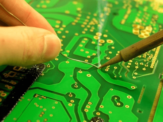
Mechanically, a PCB is necessary to support and connect all the components within a device, which are synchronized using conductive tracks—this allows electrical current to flow freely through the board and from one component to another.
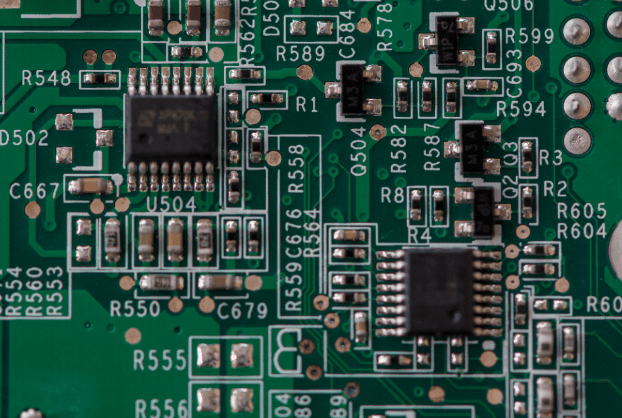
PCB components are soldered onto the board, securing them electrically and mechanically to the overall circuit. These “components” include batteries, resistors, LEDs, transistors, capacitors, and more.
Boards are typically multi-layered, consisting of layers of both conductive and non-conductive sheets. They can be single-sided with one copper layer, double-sided with a copper layer on each side of the substrate, or multi-layered, consisting of multiple layers of copper and substrate. It’s worth mentioning that multi-layer boards offer advantages such as higher component density but are also more difficult to analyze, repair, and modify.
It’s important to understand that board repair parts and operations typically use the same materials and components as those used in the original manufacturing of the hardware. There are few substitutes or alternatives, especially when it comes to reliable and conductive materials. This highlights the necessity of finding the right professional repair team with the proper resources and connections.
Which Devices Use Printed Circuit Boards?
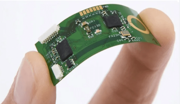
Almost all electronic devices use PCBs, from smartphones and computers to televisions and vacuum cleaners. If a device requires a power connection to operate, there is definitely some kind of circuit board inside, sometimes very small and thin.
Why Do Printed Circuit Boards Fail?
Anything can age with time and prolonged use, and printed circuit boards can develop a variety of problems. From trace damage affecting the board’s and circuit’s conductivity to component failures causing capacitors or diodes to break, there are many issues that can occur on a board.
It helps to identify and understand some of the most common PCB problems so you can address the issue in a relevant manner. This may also help those without direct experience working with boards to better maintain them.
Physical Damage
This is the more obvious option when it comes to board damage. In fact, one of the most common causes of PCB failure is physical damage to the device or its internal components. This can be almost anything related to physical stress or impact. The device in question may have been dropped from a significant height. Perhaps it was hit hard or struck forcefully by another object? It’s also possible the device was disassembled for some reason, leading to direct damage to the board.
How to Diagnose and Repair
As long as it’s not total destruction (the board shattering from a fall or breaking completely), physical damage can be repaired through a remanufacturing process. Often, this involves melting the damaged section of the board or repairing it through disassembly and reassembly. Due to the nature of most physical damage, it is unlikely that someone without printed circuit board repair experience could perform this work themselves. Repairing physical damage should only be done by trained and experienced professionals. In most cases, this requires board redesign, component re-soldering, and solder ball reflow.
Component Failure
Aside from physical damage, component failure is another common cause of printed circuit board problems. In fact, if there is no physical damage but the device won’t operate or power on, it’s almost certainly related to one of the components attached to the board.
The component itself could be anything from a capacitor and diode to a microprocessor. If there’s an issue with the component itself, and it’s damaged or non-functional, it may need to be replaced entirely. However, the problem isn’t always the component itself. Sometimes, the trace circuits can age to the point where they no longer conduct electricity due to aging, overheating, and voltage drops. It’s also possible that one or more components have completely detached from the board and need to be reinstalled.
Trace Damage
The traces on a board are conductive pathways made of silver or copper. Often, you can see issues with the traces with the naked eye, but not always. If a trace is damaged, whether from everyday use or physical damage, it can cause serious problems for the printed circuit board’s conductivity, components, and the associated device.
Some common causes of trace damage include lightning strikes, severe power surges or short circuits, metal dust contamination, overheating, and normal wear and tear.
How to Diagnose and Repair
As long as the traces aren’t particularly fine and difficult to discern, damage can usually be found simply by scanning the path. Copper and silver are inherently shiny, making breaks or damage easier to identify. Keep in mind this isn’t always the case, but it’s a good starting point.
To repair a faulty or damaged trace, simply re-solder or re-tin it with the necessary material. This reconnects the broken circuit, allowing electrical current to flow freely throughout the board.
Poor Design
While we’d love to commend every engineer or product developer, it simply doesn’t work out. Sometimes, for one reason or another, a team might cut corners when designing the board or manufacturing the necessary components. This can lead to poorly designed and constructed boards, causing problems down the line.
Power Failure
In most cases, power failure is very similar to component failure and may even be identical. Ultimately, the problem stems from a significant power failure occurring across all or part of the board. One of the PCB components may have been exposed to higher-than-normal voltage, causing it to heat up, get damaged, and explode. Or perhaps a trace fault caused a short circuit somewhere? Regardless, a power meter can be used to test each component as well as the overall conductivity of the board.
How to Check and Repair a PCB Board?
Preparation: Safety and Tools
Thorough preparation is the cornerstone of both a successful repair and personal safety before commencing any work.
Safety First:
- Work on De-energized Equipment: Always ensure the device is completely disconnected from any power source. For boards with large capacitors (e.g., in power supplies), which can retain a lethal charge even after being unplugged, discharge them safely using an appropriate resistor.
- Electrostatic Discharge (ESD) Protection: Integrated Circuits (ICs) are highly sensitive to static electricity. Use an anti-static wrist strap, an anti-static mat, and ground yourself to prevent damaging expensive components.
- Personal Protective Equipment (PPE): Use safety glasses to protect against flux splatter or component ejection, and work in a well-ventilated area to avoid inhaling solder fumes.
Essential Tools:
- Multimeter: The most important diagnostic tool for measuring voltage, resistance, and continuity.
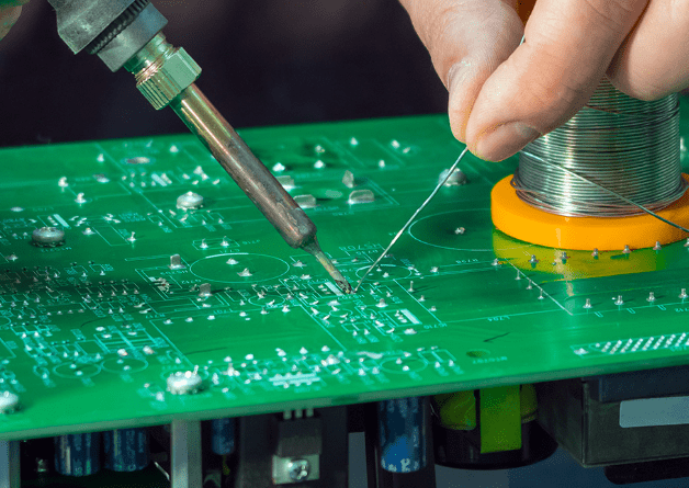
- Soldering Station and Solder: A temperature-controlled soldering station is far superior to a fixed-temperature iron. Have high-quality solder wire and desoldering braid/wick or a solder sucker ready.
- Magnification: A magnifying lamp or a bench microscope for inspecting tiny cracks, solder bridges, and component markings.
- Cleaning Tools: Isopropyl alcohol (IPA) and soft brushes for cleaning dust and grime from the board.
- Basic Hand Tools: Tweezers, flush cutters, screwdrivers, etc.
Step 1: Visual Inspection (VI)
Approximately 80% of faults can be found through careful visual inspection. Use magnification and examine the PCB from all angles.
What to Look For:
- Physical Damage: Are there any cracks or bends on the board?
- Burnt Components: Look for components that are blackened, cracked, bulging (especially capacitors), or charred. Smell for any burnt odor.
- Solder Joint Issues:
- Cold Solder Joints: Appear rough, dull, and grainy.
- Solder Bridges: Excess solder accidentally shorting two pads or pins that should not be connected.
- Cracks: Circular cracks around the solder joint.
- Trace Damage: Check copper traces for breaks, peeling, or signs of corrosion.
- Pin Corrosion: Check connectors and IC pins for green or white corrosion.
- Faulty Vias: Look for signs of looseness or detachment in the vias of through-hole components.
Step 2: Basic Testing and Fault Analysis
If the visual inspection reveals no obvious problems, it’s time to use a multimeter for deeper analysis.
Power Supply Test:
- If the board has a power input, check if the voltage is correctly reaching the board. Follow the power path and measure the input and output of regulators (e.g., 78L05) to ensure they output the correct voltage.
Continuity Test (Performed with power OFF):
- Use the multimeter’s continuity (beeper) mode to check if fuses, switches, and connectors are conducting properly.
- Check for open circuits in critical signal paths and power rails.
Resistance Test (Performed with power OFF):
- Measuring Resistor Values: Compare the measured value with the value marked on the component. The reading should be near the marked value (considering its tolerance). A reading of zero may indicate a short circuit, while an infinite reading (OL) indicates an open circuit.
- Resistance-to-Ground Test: Measure the resistance between the power rail (VCC) and ground (GND). A very low resistance (e.g., a few ohms) likely indicates a short circuit on the power rail, which is a common fault.
Common Fault Types and Their Diagnosis
Power Supply Issues
- Symptoms: The board is completely dead and unresponsive.
- Diagnosis: Start from the power input and measure the voltage backward step by step. Check fuses, diodes, rectifier bridges, and voltage regulators. Shorted capacitors are a common culprit.
Component Failure
- Capacitors: Bulging or leaking are clear signs. Even if they look intact, they can fail (reduced capacitance or increased ESR) and require a capacitance meter or ESR meter for accurate judgment.
- Resistors: Often burn out and open due to overcurrent; sometimes they discolor or crack.
- Diodes/Transistors: Test using the diode mode on a multimeter. A good diode will conduct in one direction and block in the other.
Solder Joint Problems
- Symptoms: Intermittent faults, unstable operation, especially when vibration or temperature changes occur.
- Diagnosis: Carefully inspect the solder joints of large components (like connectors, transformers) and all through-hole components for circular cracks. Re-soldering these joints is often the first step.
PCB Trace Damage
- Symptoms: Signal loss or power interruption.
- Diagnosis: Visual inspection reveals scratches or breaks. Use the multimeter’s continuity mode to trace the line and find the break.
Repair Techniques and Methods
Replacing Damaged Components
- Removal: For through-hole components, use a solder sucker or desoldering braid to remove solder before extraction. For surface-mount devices (SMD), use a hot air rework station to heat all pins simultaneously, or use a soldering iron with tweezers to heat each pin individually.
- Installation:
- Through-Hole Components: Insert the new component and solder from the bottom, ensuring the joint is smooth and cone-shaped.
- Surface-Mount Components: Use a fine or chisel tip on your iron. Position the component, tack one pin to secure it, then solder the remaining pins. For multi-pin ICs, a drag soldering technique can be used.
Repairing Broken Traces
- Gently scrape away the solder mask on both ends of the broken trace to expose the copper.
- Apply a small amount of flux and use a fine wire (e.g., enameled wire) or a piece of component lead to bridge the break. Solder it firmly in place.
- Clean the area and insulate the repair with conformal coating or hot glue to prevent short circuits.
Fixing Solder Joints and Removing Bridges
- Poor Solder Joints: Add fresh solder and flux, completely re-melt the old joint, and allow it to form a new, smooth, and shiny connection.
- Solder Bridges: Use desoldering braid. Place the braid over the bridge and apply the hot iron tip on top. The molten solder will be drawn into the braid. Remove the braid to eliminate the bridge.
Post-Repair Testing and Verification
Do not power up the board immediately after repair.
- Final Visual Check: Perform a final visual inspection to ensure there are no new solder bridges and all components are oriented correctly.
- Short Circuit Test: Measure the resistance between power and ground again to confirm you have not accidentally created a short.
- Power-Up Test: Use a variable bench power supply with current limiting. Slowly increase the voltage while monitoring the board’s current draw. If the current is abnormally high, power off immediately.
- Functional Test: If possible, install the board in the device for a full functional test. Touch key ICs to check for abnormal overheating.
Preventive Maintenance and Best Practices
Correct Operation: Ensure correct power supply polarity and that voltage is within the specified range.
Keep it Clean: Dust and grime can absorb moisture and lead to corrosion and short circuits. Regularly clean boards with compressed air and isopropyl alcohol.
Prevent Physical Stress: Avoid bending the board or subjecting it to strong vibrations.
Control the Environment: Keep devices away from excessively hot, humid, or corrosive environments.
What Does PCB Repair and Remanufacturing Include?
There are many ways to repair or maintain a printed circuit board, and the required skill level varies. However, most of the time, any operation related to the internal structure of electronic devices requires knowledge of engineering, mechanics, and basic circuits. For some of the larger devices on the market, if you operate incorrectly, it can cause serious injury or even be fatal.
For traces and conductive paths, you may need to coat, remove, or replace the necessary materials: be it copper or silver. This often requires tools like a soldering iron or hot air gun.
If the board has physical or visible damage, substrate repair is needed. This may involve melting similar materials to reshape or remodel the board, sometimes even requiring complete disassembly.
For conductor and component repairs, knowledge and skills in soldering, desoldering, BGA rework, and precise positioning may all be essential. If you’ve used or held a soldering iron before, you know that keeping your hand steady and applying solder evenly is not easy. You need extensive experience with soldering irons and desoldering to ensure components and parts are correctly installed on the board.
Of course, professionals must adhere to various IPC and ISO standards to ensure the construction and repair of electronic products and components follow the correct protocols. If you are unfamiliar or insufficiently knowledgeable about these standards, you may run into trouble later.
Ensure that any Electronic Manufacturing Service or EMS you work with understands and follows the necessary procedures.
If you are unfamiliar, an EMS is typically a circuit board repair company responsible for designing, manufacturing, testing, distributing, and repairing electronic components and internal parts. They often provide component and device repair services for OEMs or Original Equipment Manufacturers. An OEM is the company that originally designed and owns the product in question.
The entire process is called Electronic Contract Manufacturing or ECM for short.
What Materials Are Needed for PCB Repair?
As expected, most repairs require the use of the same materials (or improved ones) as the board’s official design. Reinstalling copper or silver may be necessary to fix trace paths. PCB substrates are usually made of fiberglass or epoxy resin, with copper foil bonded onto the conductive layer. They may also be made of reinforced phenolic resin, a material thinner and more paper-like than fiberglass.
Many manufacturers or repair centers also use gold, especially when replating or improving the soldered portions of the board.
The best services and repair teams can reassemble or repair a damaged motherboard to a near-original state, making the previous version and the upgraded version almost indistinguishable. Of course, this requires significant skill and experience, which can only be found in seasoned professionals.
An important part of researching and hiring a professional repair service is ensuring they have the right PCB repair materials and tools for the job. Some repair teams do not possess all the necessary equipment or tools, which leads to excessively long wait times for repairing or reassembling parts. They have to wait to receive the required materials or tools.
It is well known that many of the materials used are neither environmentally friendly nor safe. We are a long way from achieving this goal, but some scientists and cutting-edge teams are working on biodegradable PCBs that naturally decompose when discarded.
Conclusion
PCB repair is a skill that requires patience, attention to detail, and practice. Start with simple visual inspections, progressively learn to use a multimeter for diagnosis, and finally master soldering and repair techniques. By adhering to the principle of “safety first” and troubleshooting systematically, you can successfully bring many seemingly doomed electronic devices back to life. Remember, every successful repair is a valuable learning experience.


0 Comments