




A consumer PCB is a printed circuit board used in an everyday electronic product, but “consumer” does not specify its material, layer count or reliability level. Choosing one means matching the board to the product’s space, power, interfaces, environment and production requirements. A successful prototype must demonstrate those requirements inside the intended product, not merely light an LED on a bench.
This guide helps a product developer or buyer turn an idea into a reviewable board specification. It focuses on board choices and prototype tests rather than a general list of electronic devices. The outcome is a requirements sheet, a test matrix and a manufacturing handoff that different teams can check against the same design revision.
Translate the Product Into PCB Requirements
Start with the product’s constraints and convert each one into a board requirement and a verification method. “Small, reliable and inexpensive” is a goal, not a specification that a designer or supplier can approve.
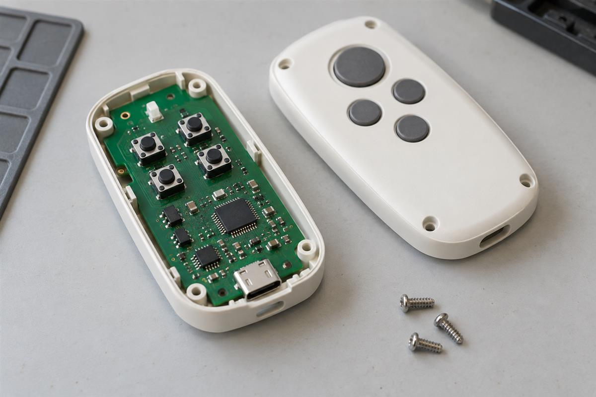
For example, a handheld controller may have fixed button positions, a battery compartment and an external connector. Those mechanical decisions constrain component placement before routing starts. A wireless sensor has a different priority: its antenna, standby current and enclosure can determine whether it meets the intended range and battery-life targets.
| Product constraint | PCB requirement to record | Evidence to request |
|---|---|---|
| Fits the enclosure | Outline, mounting points, connector positions and component-height limits | Mechanical drawing, 3D interference review and physical fit check |
| Runs from a battery | Supply range, peak current and operating-state budget | Current traces and functional checks across the agreed supply range |
| Communicates wirelessly | Module/antenna choice, keepout and final housing configuration | Communication tests in the assembled product |
| Survives normal handling | Connector support, mounting and the intended mechanical environment | A product-specific mechanical verification plan |
| Can be serviced | Accessible fasteners, connectors and replaceable subassemblies | Assembly and disassembly review |
| Can be manufactured repeatedly | Approved construction, test access and controlled files | DFM/DFA feedback, test definition and pilot-build records |
Separate a bare PCB from a PCBA. The bare board provides the patterned conductors and supporting structure; the assembly includes the fitted components. A bare-board continuity test does not exercise firmware, a charging circuit or a radio. State which deliverable you are ordering and which functions the supplier is expected to test.
Also avoid treating consumer and industrial products as a simple low-quality/high-quality split. Their required environments and service lives differ by product. A consumer appliance can have demanding safety and thermal requirements; a low-volume consumer prototype is still a consumer design. Specify the actual conditions instead of assuming them from a market label.
Choose Rigid, Flex or Rigid-Flex for a Reason
Use a rigid board when it satisfies the mechanical and electrical requirements; consider flex or rigid-flex when the interconnection or movement provides a concrete reason. A wearable device does not automatically require its main circuit board to bend around a wrist.
| Option | Useful when | Question before approval |
|---|---|---|
| Rigid PCB | Components can sit on a stable, supported board | Can the enclosure, connectors and routing be accommodated without unnecessary complexity? |
| Separate rigid boards with a cable or flex interconnect | Controls, displays or ports sit in different positions | Are connector space, assembly access and serviceability acceptable? |
| Flexible PCB | The circuit must follow a constrained shape or provide a designed flexible connection | Is it bent only during assembly, or repeatedly in use? |
| Rigid-flex PCB | Rigid component areas and integrated flexible sections solve a specific packaging problem | Does the benefit justify the fabrication, handling and validation requirements? |
A flex section formed once into an enclosure and a hinge that moves thousands of times are different applications. Define the movement, bend location, installed shape and intended life before asking for a construction. “Polyimide bends” is not proof that a finished stack of copper, adhesive and coverlay will survive the required motion. The rigid-flex manufacturing controls guide explains the construction and process checks behind that choice.
Do not choose layer count from the product category alone. Routing density, component escape, power distribution and reference continuity determine whether a proposed stackup is workable. A two-layer layout that forces poor return paths or difficult assembly may not be the least expensive finished product.
Material selection also needs a specific grade and construction where performance depends on them. A generic FR-4 description is not a complete agreement on thickness, thermal behavior or electrical properties. Have the supplier review the proposed construction before treating the layout as frozen.
Review Enclosure Fit Before Dense Routing
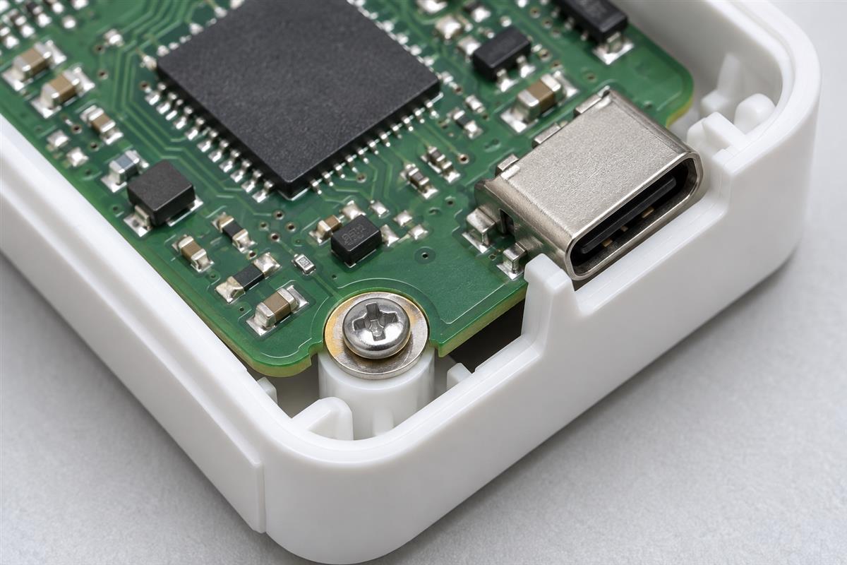
Place mechanically fixed features first and verify the board in the enclosure before optimizing routing density. A board that works electrically but prevents the lid from closing is not a usable prototype.
- Lock the physical interfaces. Confirm connector mating faces, switches, displays, indicator windows and mounting holes against the mechanical design.
- Check three-dimensional clearance. Include component height, solder joints, screw heads, cable bends and assembly-tool access, not just the board outline.
- Review mechanical loads. Consider how connector insertion force reaches the enclosure or mounting system instead of assuming solder joints should carry every load.
- Inspect sensitive regions. Check antenna space, sensor openings and heat-producing components against the complete housing and nearby parts.
- Build the fit check into the prototype plan. Record the enclosure revision and the result before releasing the next board revision.
For a wireless product, follow the actual module manufacturer’s placement and keepout guidance. As a concrete example, Espressif’s ESP32-H2 layout guidance discusses the impact of the base board and housing on the antenna and calls for final-product communication tests. Its dimensions are specific to that guidance, not a universal rule for every antenna.
A useful comparison is the same firmware and board operating first on the bench and then in the intended housing. If communication deteriorates only after assembly, investigate the enclosure, battery, wiring and antenna surroundings before changing unrelated components. Keep the test setup comparable so the result identifies a real cause.
Check Power in Every Operating State
Measure or estimate the complete product’s current in each operating state, including the transitions between states. A processor’s sleep-current specification is not the standby current of the entire assembled board.
Regulators, sensors, indicator LEDs, pull resistors and powered interfaces can remain active when firmware says the processor is asleep. Radio startup or a display update can produce short peaks that an average reading hides. Analog Devices’ system power-consumption guidance highlights active, sleep, shutdown and transition behavior as separate contributors.
A Worked Average-Current Example
Assume a teaching example in which a product draws 40 mA for 2 seconds and 0.05 mA for the remaining 58 seconds of a one-minute cycle. Assume both readings are measured at the same battery-side point and that transitions are already included:
Average current = (40 mA x 2 s + 0.05 mA x 58 s) / 60 s = 1.382 mA
If an unintended load raises the sleep reading to 1 mA, the new average is:
(40 x 2 + 1 x 58) / 60 = 2.3 mA
The average rises by about 66%, although the active current has not changed. That makes the sleep-state measurement a useful debugging target. These numbers are invented inputs for explanation, not a battery-life claim. Actual runtime also depends on usable battery capacity, cutoff voltage, temperature, self-discharge and the real duty cycle.
Keep Current and Temperature Checks Connected
Power conversion also affects heat. A linear regulator’s voltage drop and load influence its dissipation, while its own operating current matters particularly at light loads. The discussion in Analog Devices’ portable-regulator article explains why topology choice depends on the application rather than a blanket preference.
For the prototype, measure the relevant rails during startup and the heaviest intended operating mode, then check temperatures in the actual enclosure. Use the components’ operating limits and an appropriate thermal assessment; “it feels warm” is not an acceptance criterion. Battery charging, protection and any mains-connected circuitry need a suitable product-safety review, not improvised stress tests.
Test the Prototype as a Finished Product
Turn each product requirement into a test with a defined setup, expected result and recorded outcome. A prototype that boots once demonstrates less than a product that works across its specified conditions.
| Test area | What to verify | Record with the result |
|---|---|---|
| Assembly and connectivity | Correct components, polarity, soldering and intended electrical connections | Board revision, BOM revision and inspected exceptions |
| Startup and supply variation | Reliable initialization and behavior over the approved input range | Supply settings, firmware version and rail measurements |
| Operating modes | Buttons, sensors, display, communication and relevant combinations | Mode, connected peripherals and pass/fail criteria |
| Low-power behavior | Sleep entry, wakeup and actual battery-side consumption | Current waveform or suitable measurement, timing and configuration |
| Enclosed operation | Fit, cable routing, temperature and wireless behavior | Housing revision, orientation and ambient conditions |
| Handling and interfaces | Product-specific connector, mechanical and ESD-related requirements | Agreed procedures and results from appropriate test personnel |
| Recovery | Intended response to interrupted power or a communication failure | Failure condition, recovery behavior and any retained-state issues |
The matrix is a planning tool, not a claim that every product needs identical tests or limits. Select the relevant tests with the product engineering and compliance teams. A supplier’s bare-board electrical test, assembly inspection and your final functional test address different failure modes. The assembly testing coverage guide explains what AOI, X-ray, ICT and functional tests can and cannot establish.
When a unit fails, preserve the board identifier and exact configuration. Reproduce the symptom, isolate a suspected cause and change one relevant variable where practical. “Sometimes resets” becomes useful when the record says which mode, supply condition and attached accessory trigger the reset.
Do not assume one passing prototype establishes production reliability. A pilot build can reveal assembly variation, difficult test access and repeatability problems that a hand-reworked sample conceals. Agree how units are selected and which evidence is required rather than treating any arbitrary sample count as sufficient.
Compare Production Cost Without Removing Needed Checks
Compare quotations for the same released design and test scope. A lower price can reflect a different material, excluded components, omitted programming or a smaller verification package rather than a genuine like-for-like saving.
Ask whether the quotation includes bare-board fabrication, components, assembly, programming, fixtures, functional testing, packaging and any agreed reports. Separate one-time setup costs from recurring unit costs. Also state the quantity and allowed component substitutions.
Cost reduction should follow the product constraints. A more accessible package may simplify assembly and inspection; a removable connector may improve serviceability but add parts and assembly time. A rigid-flex construction may remove connectors but introduce different fabrication and handling requirements. Evaluate the complete product effect instead of choosing the lowest board-only price.
Do not remove test points solely to save space without reviewing how the board will be programmed and tested. If a supplier must manually probe tiny pads or repeatedly disassemble the housing, that hidden labor belongs in the cost comparison. Resolve test access before the layout is released.
Prepare a Controlled Handoff to the Supplier
Send a consistent revision-controlled package and identify what may change only with approval. A supplier should not have to infer the product’s critical requirements from unrelated emails.
- Fabrication files, drills, outline and approved stackup.
- Assembly BOM with manufacturer part numbers and substitution rules.
- Placement data, polarity information and assembly drawings where needed.
- Mechanical constraints, connector positions and relevant enclosure drawings.
- Programming files, version information and a safe, agreed programming method.
- Functional-test procedure, fixture responsibilities and measurable acceptance criteria.
- Quantity, packaging and traceability requirements.
- A contact responsible for approving deviations and closing DFM/DFA questions.
Before approving production, check that a late component substitution or mechanical change has not invalidated the prototype results. A replacement regulator can change startup or standby behavior; a new enclosure can affect antenna performance. Re-test the affected requirement rather than assuming the part is interchangeable because its headline specification looks similar.
Consumer PCB Design Questions
Is a Consumer PCB Always a Low-Cost Two-Layer Board?
No. The product’s routing, packaging and electrical requirements determine the construction. Market category alone does not set layer count or acceptable quality.
Does Every Wearable Need a Flexible Main Board?
No. A wearable can use a rigid board inside a housing, with a separate flexible connection where needed. Choose flex for an actual shape or movement requirement and validate that use.
Can I Order Assembly With Only Gerber Files?
Gerbers do not identify all fitted parts or assembly requirements. Provide the BOM, placement information and other agreed assembly and test inputs in addition to fabrication data.
Does a Supplier Certificate Guarantee Defect-Free Boards?
No. Check the certificate’s scope and the evidence relevant to your order. Inspection, testing, traceability and agreed acceptance criteria remain necessary.
Can a Radio Module Replace End-Product RF Testing?
No. The host board, antenna placement, enclosure and operating configuration affect the final product. Follow the module’s integration instructions and establish the applicable product-level verification requirements.
Why Does My Board Use More Current Than the Datasheet?
The datasheet may describe one component under specific conditions. Measure the whole board and check peripherals, regulator current, firmware configuration and transitions before assuming the component is faulty.
Should Prototype Rework Be Carried Into Production?
Not as an undocumented workaround. Incorporate approved corrections into the released design or a controlled process instruction, then verify the resulting build.
Can a Passed Functional Test Replace a Safety Review?
No. Demonstrating that a product operates normally does not establish safety under all relevant conditions. Use the applicable product requirements and qualified review for that separate assessment.
Ready to review a consumer-electronics board? Send the fabrication data, BOM, placement files, quantity and prototype test requirements through PCBtry’s contact page. Ask which construction, assembly and verification requirements can be supported, and resolve open deviations before production.



0 Comments