




The Honeywell XNX Universal Transmitter is a configurable platform for fixed industrial gas detection. It can work with several sensor technologies and can provide 4–20 mA/HART plus selected optional outputs, but the exact sensor, interface, approval and power requirement depend on the complete part number and installed option.
If you searched for “xnx xnx honeywell analytics,” the repeated XNX is not a separate model. The official product family is the Honeywell XNX Universal Transmitter. Use the nameplate, complete part number and current Honeywell documentation—not the family name alone—when selecting, wiring or replacing a unit.
Editorial disclosure: Honeywell, Honeywell Analytics, XNX, Sensepoint and Searchpoint are trademarks of their respective owner. PCBTRY is not presented as a Honeywell distributor, authorized repair center or manufacturer of XNX equipment. This independent guide summarizes publicly documented product information and does not replace the current product manual, safety manual, certificate or site procedure.
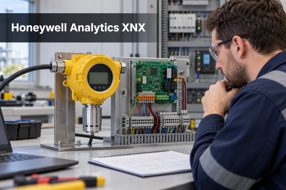
What Is the Honeywell XNX Universal Transmitter?
The XNX is a common transmitter platform that connects compatible gas-sensing technologies to a plant control or safety system. Honeywell documents three transmitter personalities: millivolt (mV), electrochemical (EC) and infrared (IR). This platform approach can standardize the user interface and field wiring across different detection duties, while the selected sensor and option board determine what the actual unit can measure and communicate.
A working installation combines a transmitter personality, compatible sensor, enclosure and entry arrangement, output option, power supply, accessories and applicable approvals. For that reason, “XNX” is not enough information for a replacement order.
Honeywell XNX Technical Specifications
The table summarizes family-level reference values from Honeywell’s public XNX data sheet. Values can differ by personality, sensor, option, region and document revision, so verify the current manual and exact part number before design, purchase or installation.
| Parameter | Published XNX Reference | What to Verify |
| Transmitter personalities | mV, electrochemical and infrared | Personality and compatible sensor technology |
| Input voltage | EC and mV: 16–32 VDC; IR: 18–32 VDC; 24 VDC nominal | Sensor configuration, cable loss and protection-device drop |
| Maximum power examples | EC toxic: 6.2 W; mV catalytic or IR cell: 6.5 W; IR with Searchpoint Optima Plus: 9.7 W; IR with Searchline Excel receiver: 13.2 W | Exact sensor and transmitter configuration |
| Standard output | Configurable 4–20 mA with HART; source, sink or isolated operation | Loop mode, load, polarity and diagnostic-current mapping |
| Optional outputs | Relay, Modbus RTU or FOUNDATION Fieldbus | Installed module; options are not present in every unit |
| Terminal conductor range | Approximately 0.5–2.5 mm², subject to terminal configuration | Wire, ferrule, gland and installation requirements |
| Enclosure and weight | Painted aluminum alloy, about 2.8 kg; 316 stainless steel, about 5 kg | Ordered enclosure, mounting and corrosion environment |
| Approximate dimensions | 160 × 197 × 114 mm | Sensor and accessories can change the installed envelope |
| Ingress protection | IP66; NEMA 4X listed in the data sheet | Glands, seals, entries, mounting and approved configuration |
| Published environment | −40 to +65 °C; 0–99% RH non-condensing; 90–110 kPa | Sensor-specific and approval-specific limits may be narrower |
These values are not interchangeable across every configuration. An IR arrangement can have a different supply requirement and power demand from an EC toxic-gas arrangement. Request the complete configured part number and corresponding documents rather than relying on a family brochure.
How Does the XNX Transmitter Work?
The XNX conditions the signal from a compatible sensing technology, applies configured measurement and diagnostic logic, displays local information and sends status to a controller. The sensing principle belongs to the selected sensor: catalytic bead sensors respond to combustible gas through oxidation effects, electrochemical cells generate a reaction-related signal for a target gas, and infrared sensors measure gas absorption at selected wavelengths.
The standard 4–20 mA channel can carry the measurement and documented fault or inhibit levels, while HART adds digital communication on the analog loop. Optional hardware can provide relay contacts, Modbus RTU or FOUNDATION Fieldbus. Do not assume that every unit supports every protocol shown in family literature.
Which Sensor Personality and Output Should You Choose?
Choose the sensor personality from the target gas and approved sensing arrangement, then choose outputs from the control-system architecture. This table is a selection guide, not a compatibility certificate.
| Choice | Reason to Consider It | Selection Checks |
| mV personality | Compatible catalytic-bead or documented millivolt sensor arrangements | Gas, sensor, distance, wiring, calibration and approval |
| EC personality | Compatible toxic-gas or oxygen electrochemical sensing | Target gas, range, cross-sensitivity, cell life and environment |
| IR personality | Compatible infrared point or open-path sensing | Sensor, power, path or mounting, contamination and approval |
| 4–20 mA/HART | Analog measurement with digital configuration or diagnostics | Source/sink/isolated mode, loop load and HART compatibility |
| Relay option | Local alarm or fault contacts | Contact ratings, alarm philosophy and energized state |
| Modbus RTU | Digital communication to a compatible host | Address, baud rate, framing, topology and register support |
| FOUNDATION Fieldbus | Compatible fieldbus architecture | Segment engineering, separate power, files and host compatibility |
The selection sequence should be: target gas and range; sensing principle; environment and hazardous-area requirements; output and host compatibility; enclosure and cable entry; accessories; power and cable calculation; calibration and maintenance plan; then exact ordering code.
Where Is the Honeywell XNX Used?
XNX transmitters are intended for fixed gas-detection duties where continuous monitoring and integration with a control or safety system are required. Application suitability depends on the selected sensor and approvals, not merely on the XNX enclosure.
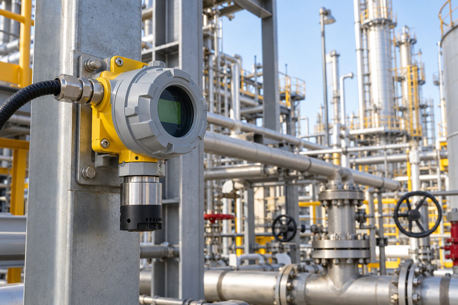
- Oil, gas and petrochemical facilities: monitoring around process equipment, storage and transfer areas.
- Refineries and chemical plants: fixed monitoring where releases can create fire, toxicity or oxygen risks.
- Power generation and utilities: monitoring selected fuel, process or hazardous gases.
- Water and wastewater: monitoring site-specific hazards such as hydrogen sulfide with a suitable sensor.
- Industrial manufacturing: fixed detection near processes that use, release or store hazardous gases.
Gas behavior, ventilation, temperature, obstructions, release points, occupancy and maintenance access affect location. A qualified gas-detection or safety engineer should establish coverage and alarm philosophy.
How Should XNX Be Installed and Used?
Installation should follow the current Honeywell technical manual, approval conditions, local electrical codes and the site safety procedure.
- Confirm the complete definition: part number, sensor, personality, enclosure, entry, output and regional approval.
- Confirm location and orientation: use the target gas, release scenario, airflow, access and environment.
- Calculate power at the transmitter: include supply tolerance, cable resistance, maximum current and protection losses.
- Match the interface: verify 4–20 mA mode, relay function or digital settings before termination.
- Use suitable entries and sealing: environmental protection depends on correct glands, plugs and seals.
- Commission and calibrate: use the specified gas, concentration, flow arrangement and procedure.
- Test alarms end to end: verify normal, inhibit, warning, over-range and fault interpretation.
- Document maintenance: record calibration, proof tests, replacements, faults and configuration changes.
Honeywell XNX vs Sensepoint XCD
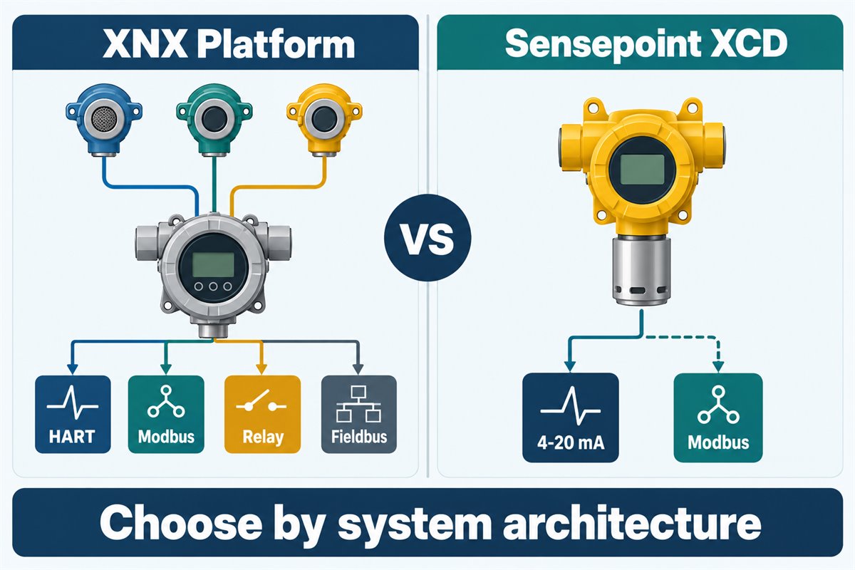
XNX is a configurable universal transmitter platform, whereas Sensepoint XCD is an integrated fixed gas-detector family with a more defined architecture. Neither is automatically better; the decision depends on gas, sensor, outputs, installed base, approvals and maintenance.
| Decision Factor | Honeywell XNX | Honeywell Sensepoint XCD |
| Approach | Universal transmitter with mV, EC or IR personality and selected options | Integrated fixed detector family with defined sensor configurations |
| Analog output | 4–20 mA with HART; source, sink or isolated | 4–20 mA source or sink documented |
| Digital communication | HART standard; optional Modbus RTU or FOUNDATION Fieldbus | Optional Modbus RTU documented |
| Published supply | EC/mV 16–32 VDC; IR 18–32 VDC | Verify the exact XCD model data sheet |
| Best-fit question | Is a configurable common platform needed across sensor technologies or outputs? | Is an integrated detector within the documented XCD range preferred? |
| Replacement implication | Match personality, sensor and option configuration | Not automatically a drop-in XNX replacement |
Are There Alternatives or Replacements for Honeywell XNX?
There may be suitable alternative fixed gas detectors, but there is no universal drop-in replacement for every XNX configuration. Sensepoint XCD, other Honeywell families and comparable products from established gas-detection manufacturers may satisfy a similar duty, yet functional similarity does not prove mechanical, electrical, communication or certification compatibility.
Before considering a replacement, compare:
- target gas, range, units, sensing principle, response and cross-sensitivity;
- power range, maximum consumption, cable calculation and environmental limits;
- 4–20 mA mode, fault levels, HART, relays and digital protocol;
- housing, dimensions, mounting, cable entries and weather protection;
- hazardous-area, functional-safety, marine or regional approvals;
- controller configuration, register map, alarm logic and maintenance tools;
- proof-test interval, calibration, service support and lifecycle status.
A similar product can still require wiring, mounting, controller and safety-document changes. Unless the manufacturer explicitly documents interchangeability for the exact ordering codes, describe it as a potential replacement that requires engineering verification, not a direct replacement.
Common Selection and Maintenance Mistakes
Most avoidable errors result from treating a configurable family as one fixed model.
- Ordering “Honeywell XNX” without the complete part number and options.
- Assuming every transmitter includes Modbus, relays and Fieldbus.
- Selecting from gas name alone without checking range, cross-sensitivity and environment.
- Using nominal 24 VDC without worst-case cable and load calculations.
- Assuming IP66 remains valid with unsuitable entries, plugs or seals.
- Copying approvals from a different sensor, enclosure or regional configuration.
- Calling XCD or another detector a direct replacement without full verification.
- Changing a sensor without updating calibration, controller scaling and proof-test records.
Frequently Asked Questions
Is “xnx xnx honeywell analytics” an official model?
No. The official family is the Honeywell XNX Universal Transmitter. The repeated term is a search variation, not a separate model.
What gases can XNX detect?
The platform supports compatible catalytic, electrochemical and infrared arrangements for various combustible, toxic and oxygen duties. The installed sensor defines the actual gas and range.
Does every XNX include HART?
Honeywell documents HART on the standard configurable 4–20 mA output. The loop and host equipment must also support HART.
Does every XNX include Modbus?
No. Modbus RTU is optional. Confirm the installed output module and protocol settings.
What power supply does XNX require?
The data sheet lists 16–32 VDC for EC and mV and 18–32 VDC for IR, with 24 VDC nominal. Verify configuration power and cable loss.
Can XNX operate as a 4–20 mA source or sink?
Honeywell documents source, sink and isolated modes. The transmitter and receiving system must agree on topology, polarity, load and diagnostic behavior.
Is Sensepoint XCD a direct replacement?
Not automatically. Verify gas, range, output, power, mounting, diagnostics and approvals. Treat it as a potential replacement requiring engineering verification.
Can an XNX sensor be changed to detect another gas?
Do not assume a sensor change alone converts the system. Compatibility depends on personality, sensor, configuration, approvals, firmware and calibration.
How often should XNX be calibrated?
No single interval suits every site. Follow current Honeywell instructions, legal requirements, risk assessment, sensor history and environment.
Does IP66 make every installation IP66?
No. Protection depends on the approved enclosure, correct entries, glands, seals, mounting and maintenance.
Official References and Safety Boundary
Product details were checked against Honeywell’s public XNX product page, XNX data sheet, XNX engineering specifications and Sensepoint XCD page.
Documents, approvals and availability can change. Obtain the current manual and certificate for the exact part number. Installation, calibration, detector placement, alarm settings, proof testing and hazardous-area work require qualified personnel under applicable site and legal requirements.


0 Comments