
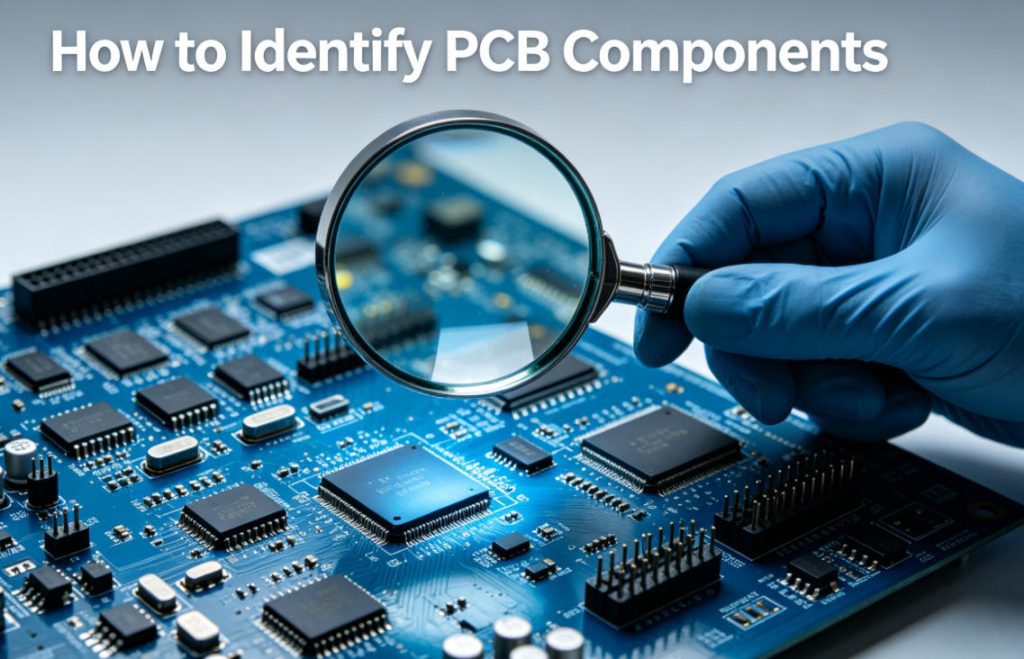
How to Identify PCB Components Accurately on Circuit Boards?
Learning how to identify pcb components allows engineers and technicians to diagnose circuit faults, complete prototype debugging, and verify assembly quality. This guide explains simple and professional methods for how to identify pcb components without advanced testing equipment.
Most electronic technicians rely on visual marking inspection, component shape recognition, and multimeter testing to classify PCB parts. These beginner-friendly techniques reduce judgment errors during daily circuit maintenance and design review.
What basic preparations are needed before identification?
- High magnification magnifying glass for tiny silkscreen reading
- Digital multimeter for electrical characteristic verification
- Clear PCB schematic or BOM reference file
What Are The Most Common Types of PCB Components to Recognize?
All printed circuit boards contain standardized passive and active components. Every technician must master visual identification for mainstream electronic parts to speed up circuit analysis and troubleshooting workflows.
Common components include resistors, capacitors, inductors, diodes, transistors, and integrated circuits. Each category has fixed physical shapes and silkscreen symbols for fast visual differentiation.
Passive Components
- Resistors: Black or beige rectangular chips with resistance codes
- Capacitors: Brown ceramic blocks or cylindrical electrolytic shells
- Inductors: Coiled metal wires or magnetic strip chips
Active Components
- Diodes: Black tiny chips with one marked polarity line
- IC Chips: Square multi-pin packaged microcontrollers
How to Tell Passive Components Apart on Bare PCBs?
Passive components account for over 70% of PCB surface parts. You can quickly distinguish resistors, capacitors, and inductors through appearance, color, and surface markings without professional testing tools.
Misjudgment of passive parts often causes debugging failure and rework. The comparison table below simplifies passive component identification for hardware teams.
| Component Type | Surface Color | Typical Shape | Silkscreen Code Feature |
| Resistor | Black / Beige | Flat rectangle | 3-4 digit resistance code |
| Ceramic Capacitor | Dark Brown | Square chip | No printed numbers |
| Inductor | Silver / Black | Strip or coil shape | Magnetic shell marking |
How to Identify Active Semiconductor Components?
Active components control circuit signal transmission and power switching. Technicians can identify semiconductors by pin quantity, package type, and surface printed model numbers.
IC chips and transistors have standardized packaging appearances. Even without BOM files, engineers can judge component functions based on industry common packaging rules.
Simple Identification Skills
- SOT-23 packages usually represent transistors or MOS tubes
- QFP square packages belong to main control microchips
- Triangular marks indicate diode polarity direction
What Silkscreen Markings Help Identify PCB Components?
PCB silkscreen is the most intuitive identification basis. Standard manufacturers print unified reference symbols near each component to help staff confirm electronic parts rapidly.
All formal circuit boards follow universal marking rules. Learning fixed prefix codes can greatly improve component recognition efficiency for beginners.
Universal Silkscreen Prefix Codes
- R = Resistor, C = Capacitor, L = Inductor
- D = Diode, Q = Transistor, U = Integrated Circuit
- J = Connector, SW = Switch Interface
Which Four Industries Widely Apply Accurate PCB Component Identification?
Component identification ability is essential for industrial maintenance, product iteration, and quality inspection. The four most popular industries include consumer electronics, automotive electronics, medical electronics, and industrial control.
Each industry uses unique PCB types and component layouts. Precise component recognition ensures stable product operation and compliance with industry certification standards.
Industry Application Cases
- Consumer Electronics: Double-sided SMT PCB for smart watches; accurately identify tiny resistors to fix power consumption failure.
- Automotive Electronics: Thick-copper automotive PCBA; distinguish high-power MOS tubes to ensure vehicle energy management safety.
- Medical Electronics: HDI high-density PCB for monitoring devices; identify miniature IC chips to guarantee signal stability.
- Industrial Control: Multilayer industrial motherboard; classify power inductors to prevent automated equipment overload damage.
What Common Mistakes Occur When Identifying PCB Components?
Many technicians confuse blank capacitors with blank resistors or misjudge chip diodes. These frequent errors lead to wrong replacement parts and repeated circuit failures.
Most identification mistakes come from insufficient observation of polarity marks and package differences. Summarized error points help engineering teams avoid basic technical pitfalls.
Typical Errors
- Confusing unmarked ceramic capacitors with fixed resistors
- Ignoring polarity marks of electrolytic capacitors
- Treating SOT-23 MOS tubes as ordinary signal transistors
How to Use Testing Tools to Verify PCB Components?
Visual identification cannot confirm component electrical performance. A digital multimeter is the most convenient tool to verify resistance, capacitance, and diode on-off characteristics.
Simple testing steps take less than one minute per component. This method effectively eliminates misjudgment caused by similar appearance between different chips.
Basic Testing Steps
- Power off the PCB completely to avoid current interference
- Adjust multimeter gear corresponding to component type
- Contact two pins and record real electrical data
How Can DFM Reports Improve Component Layout Recognition?
A professional free DFM report clearly marks every component position, package size, and welding requirement on PCBs. It helps designers and inspectors recognize parts before mass production.
Engineers can optimize component layout through DFM feedback. Combining on-demand customization services avoids irregular component placement that increases identification difficulty.
What Practical Skills Speed Up PCB Component Recognition?
Senior technicians summarize universal identification rules for daily work. Simple habits can greatly shorten recognition time for complex multilayer circuit boards.
These practical skills are suitable for hardware designers, maintenance personnel, and supply chain inspectors without advanced professional knowledge.
Efficient Recognition Tips
- Observe silkscreen prefix first before checking appearance
- Classify components by size from large to small
- Mark special semiconductor parts for secondary confirmation
FAQ – Frequently Asked Questions About Identifying PCB Components
How do beginners identify PCB components without BOM files?
Beginners can rely on silkscreen prefixes, component colors, and standard package shapes. Passive components are classified by appearance, while active chips are distinguished by pin quantity.
Why cannot I see numbers on some SMT resistors?
Ultra-small 0201 and 01005 chips cancel surface printing to save space. You need multimeter testing or original design documents to confirm specific resistance parameters.
Is it hard to identify components on high-density HDI PCBs?
Yes, HDI boards contain tiny components and dense wiring. Professional magnifying equipment and complete DFM analysis files are required for accurate identification.
Can component identification reduce PCB production failure rate?
Absolutely. Accurate component checking prevents wrong part placement. Complete pre-production inspection effectively lowers assembly defects and rework probability.
Do customized PCBs have unique component marking rules?
Customized circuit boards follow universal industrial marking standards. Reliable manufacturers keep unified silkscreen codes to maintain identification consistency.
Why Learn PCB Component Identification for Electronic Projects?
Component identification runs through PCB design, production, inspection, and maintenance stages. Mastering how to identify pcb components improves overall project efficiency and reduces human error risks.
Standardized component layout and clear silkscreen printing directly enhance recognition efficiency. Choosing qualified PCB manufacturers guarantees clear identification conditions for every circuit board.
Get Custom PCB Solutions With Clear Component Markings From Thindry
Thindry provides high-quality PCB fabrication and PCBA services for users learning how to identify pcb components. We maintain clear silkscreen printing and standardized component layout for every circuit board.
We support full on-demand customization for industrial, automotive, medical, and consumer electronic PCBs. Every order includes a free DFM report to optimize component arrangement and avoid recognition confusion.
Whether you need prototype circuit boards or mass production PCBA products, our engineering team provides stable and compliant manufacturing solutions. Contact us for technical consultation and project cooperation: sales@pcbtry.com


0 Comments