
Learning how to read a PCB board is essential for electronics work, and this guide teaches you the skills clearly and practically. Mastering how to read a PCB board helps with assembly, troubleshooting, and quality control across all electronics industries.
What Are the Basic Components to Identify When Learning How to Read a PCB Board?
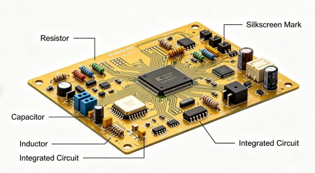
When learning how to read a PCB board, start with the most common components. These parts appear on nearly every PCB and follow universal labeling rules.
| Component Type | Silk Screen Symbol | Visual Features | Main Function |
|---|---|---|---|
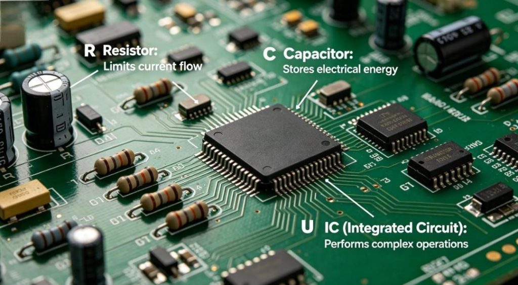
| Resistor | R + Number | Small rectangular black chip | Controls electrical current |
| Capacitor | C + Number | Rectangular or cylindrical | Stores energy and filters noise |
| Integrated Circuit | U / IC + Number | Large square chip with pins | Processes signals and controls functions |
| Diode / LED | D / LED + Number | Small with polarity marks | Directs current or indicates status |
| Connector | J / CN + Number | Multi-pin port for external links | Connects PCB to other devices |
How to Read a PCB Board’s Silk Screen Symbols and Labels?
Silk screen labels are the primary guide when you read a PCB board. They use standard marks to show components, power, and test points.
Key Silk Screen Labels
- Power: VCC, VDD, +3V3, +5V
- Ground: GND, AGND, DGND
- Polarity: +, -, dot for IC Pin 1
- Test Points: TP + Number
- Jumpers: JP + Number
All labels follow global standards and are printed for high visibility during assembly and inspection.
How to Read a PCB Board’s Layers (Top, Bottom, Inner Layers)?
To fully read a PCB board, you must understand its layers. Layers manage signals, power, and ground in both simple and complex boards.
Main PCB Layers
- Top & Bottom Layers: Visible copper traces
- Silk Screen Layer: Text and component labels
- Solder Mask Layer: Protective green/black coating
- Inner Layers: Hidden power and ground planes
Vias are small metal holes that connect layers and maintain electrical continuity.
How to Read a PCB Board for Consumer Electronics?
Consumer electronics use compact PCBs, and learning to read a PCB board in this field helps diagnose issues quickly.
Smartphone PCBs use tiny ICs and dense traces. Reading labels like U1 (main processor) and J_BAT (battery connector) helps fix power and display problems.
TWS headphone PCBs use flexible materials. Reading Bluetooth IC and LED labels helps resolve audio and connection failures.
How to Read a PCB Board for Medical Electronics?
Medical devices require high reliability, so knowing how to read a PCB board ensures safety and stability.
Ultrasound and patient monitor PCBs use clearly marked power circuits. Reading voltage labels and MOSFET markers helps identify power failures fast.
Medical sensor PCBs rely on accurate signal paths. Reading sensor connectors and filter components helps fix measurement errors.
How to Read a PCB Board for Industrial Control?
Industrial control systems use rugged, multi-layer PCBs. Learning to read a PCB board helps maintain PLCs and sensors.
PLC PCBs have large main ICs and relay markers. Reading K-series labels helps fix motor and output control issues.
Temperature sensor PCBs use marked sensing ICs and capacitors. Reading these labels helps resolve unstable readings.
How to Read a PCB Board for Automotive Electronics?
Automotive PCBs work in harsh environments. Knowing how to read a PCB board supports vehicle system repairs.
Engine Control Module PCBs use clearly labeled microcontrollers and MOSFETs. Reading these marks helps diagnose engine performance issues.
Car display PCBs use driver ICs and backlight LED labels. Reading these paths helps fix dim or non-functional screens.
What Are Common Mistakes When Learning How to Read a PCB Board?
Beginners often make simple errors when learning to read a PCB board. These mistakes lead to misdiagnosis and component damage.
Mistake 1: Misreading Polarity
Swapping positive and negative damages capacitors and LEDs. Always check silk screen polarity marks.
Mistake 2: Confusing Ground Types
Analog ground (AGND) and digital ground (DGND) must stay separate. Mixing them causes signal interference.
Mistake 3: Ignoring Trace Width
Thick traces carry high current; thin traces carry signals. Misjudging them leads to wrong troubleshooting.
How to Read a PCB Board’s Gerber Files?
Gerber files show full PCB structure. Learning to read a PCB board through Gerber files supports design and production checks.
Common Gerber Extensions
- GTL: Top copper layer
- GBL: Bottom copper layer
- GTO: Top silk screen
- GTS: Top solder mask
- GM: Mechanical outline and size
We support custom solutions + free DFM reports to help you analyze Gerber files and ensure reliable production.
How to Read a PCB Board for Troubleshooting?
Reading a PCB board properly speeds up repairs. Follow this structured method to find faults efficiently.
- Check power labels (VCC, GND) for continuity.
- Inspect components for physical damage.
- Trace signal paths from faulty parts.
- Use test points to verify voltage levels.
This method works for all industries and reduces diagnostic time significantly.
How to Tell Different PCB Types When Reading Them?
Different PCB types have unique visual traits. Learning to read a PCB board includes identifying board material and structure.
| PCB Type | Visual Features | Reading Tips |
|---|---|---|
| Rigid PCB (FR-4) | Stiff, green mask, firm structure | Look for clear layers and large ground planes |
| Flexible PCB | Thin, bendable, lightweight | Focus on compact traces and small components |
| Aluminum PCB | Metal base, high heat dissipation | Used for LEDs and power systems |
| HDI PCB | Ultra-dense components, tiny vias | Used in smartphones and high-tech devices |
FAQ: Common Questions About How to Read a PCB Board
1. Do I need tools to read a PCB board?
No special tools are required. A magnifying glass helps with small boards, but most labels are readable with the naked eye.
2. What do R1, C5, and U1 mean on a PCB board?
These are component IDs: R for resistor, C for capacitor, U for IC. Numbers help locate parts in the BOM.
3. How to read a PCB board with faded silk screen?
Use component shape, size, and position to identify parts. Standard footprints match common electronic components.
4. Can I read a PCB board without circuit knowledge?
Yes. You can identify components and trace paths without advanced circuit theory.
5. How to find power and ground lines on a PCB board?
Power lines use thick traces labeled VCC. Ground uses large copper areas labeled GND.
6. How to check short circuits by reading a PCB board?
Look for touching traces, solder bridges, or burnt areas. These signs indicate short circuits.
How to Read a PCB Board for Mass Production Quality Control?
Reading a PCB board in mass production ensures consistency and reduces defects.
Verify components match labels, check trace continuity, and confirm no assembly errors.
We support custom solutions + free DFM reports to optimize your PCB quality control process.
How to Improve Your Skills to Read a PCB Board Faster?
Practice regularly to master how to read a PCB board quickly and accurately.
- Start with simple PCBs before complex designs
- Memorize standard symbols and labels
- Use Gerber viewers to practice layer reading
- Troubleshoot real-world small PCB issues
We provide professional PCB solutions and services for how to read a PCB board. We support custom orders and offer free DFM reports. Contact us at sales@pcbtry.com to place your order. Thindry is your trusted partner for PCB manufacturing and design.


0 Comments