
An LED PCB is the core of every lighting product, yet many engineers notice problems only after the system is installed. The light becomes dimmer over time. Color changes slowly. High-power modules heat up faster than expected. Drivers fail early. These issues often link back to the PCB rather than the LED itself.
A well-designed LED PCB keeps the module cool, stable, and bright. It supports the LED’s electrical needs and carries heat away from the chip in a clean path. When the board has the right material, layout, and testing standard, the entire lighting system operates with calm consistency. This guide gives you a clear and practical view of LED PCBs, focusing on materials, thermal performance, layout skills, and real applications.
LED PCB Design & Manufacturer
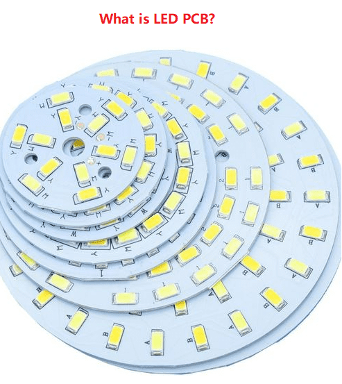
What is an LED PCB?
An LED PCB is a printed circuit board used to mount LED chips and manage their electrical and thermal behavior. LEDs create heat as they work. The PCB must move this heat away from the LED junction quickly. If heat stays trapped, the LED becomes unstable and ages faster.
A typical LED PCB contains copper pads for soldering, traces to carry current, and a substrate that spreads heat. High-power LEDs often require metal-core PCBs, while low-power LEDs can work on FR4. The choice depends on power density, the size of the lamp, and the lifetime expectations.
LED PCBs are used in indoor lighting, outdoor fixtures, automotive lamps, displays, medical devices, and many other systems where steady brightness and long lifespan matter.
Common Types of LED PCBs
Different lighting applications need different PCB structures. Below are the most common options:
1. Aluminum LED PCB (MCPCB)
This is the most widely used LED PCB type. It has a metal base—usually aluminum—and a thin dielectric layer with high thermal conductivity. It spreads heat across the plate and transfers it to the heatsink. MCPCBs are used for street lights, flood lamps, downlights, and panel lights.
2. FR4 LED PCB
FR4 boards are common for small indicator LEDs, low-power backlights, or decorative lighting. Cost is low. Thermal conductivity is also lower. Designers often add thermal vias to push heat away.
3. Copper-based LED PCB
Copper substrates move heat faster than aluminum. These boards support very high-power LEDs such as UV curing lamps, surgical lighting, or industrial spotlights. They cost more but offer unmatched thermal performance.
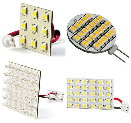
4. Flexible LED PCB
Flexible PCBs allow designers to bend or curve the board. LED strips, ring lights, and wearable electronics often rely on flex circuits. They are thin, light, and easy to shape.
Thindry circuit offers various LED PCBs covering all applications, like education, consumer electronics, street light, pool light, high bay light and so on.
What are the components of LED PCB?
A typical LED PCB is built from several layers and parts that work together:
- Copper layer for electrical paths
- Dielectric layer for insulation
- Metal substrate (aluminum or copper) for heat spreading
- Surface finish such as ENIG, OSP, or silver
- LED pads for soldering LED chips
- Resistors or drivers depending on circuit design
- Thermal vias (in FR4 boards) to push heat downward
- Solder mask to protect traces
- Silkscreen to label components and polarity
What are the characteristics of LED PCB?
LED PCBs carry several special features that are not found in normal boards:
- High thermal conductivity
- Stable electrical performance
- Strong bonding between layers
- Resistance to moisture and yellowing
- Smooth heat path from LED to metal base
- Lightweight structure with good strength
- Long service life even under continuous lighting
These characteristics help LEDs operate with lower junction temperature, which directly improves brightness consistency and lifespan.
Why Is Thermal Management So Critical in LED PCBs?
LEDs convert part of their power into heat. If heat cannot escape smoothly, the LED junction temperature rises. This leads to fast brightness decay, color drift, and shorter life. High temperature also stresses solder joints and may cause early failures.
Heat travels from the LED chip → solder joint → copper pad → dielectric → metal substrate.
Every layer must be optimized.
Good thermal management brings clear benefits:
- Cooler LED junction temperature
- Higher luminous efficiency
- Better color stability
- Longer lifetime
- More reliable performance in closed fixtures
This is why high-power LED designs usually prefer aluminum or copper metal-core PCBs.
How to Design LED PCB Layout for Better Heat?
Effective LED PCB thermal design begins with controlling the heat path. Every step—from pad geometry to copper distribution—affects the LED junction temperature. The following design methods are widely used in medium- and high-power LED systems.
1. Maximize Copper Area Around LED Pads
Copper has high thermal conductivity (~385 W/m·K). Larger copper pours surrounding each LED reduce spreading resistance. A continuous copper region lowers the temperature gradient between the LED pad and the PCB surface. Avoid fragmented copper zones or isolated traces, which create thermal bottlenecks.
2. Use Dense Thermal Vias for FR4-Based LED Boards
FR4 has low thermal conductivity (~0.3 W/m·K). Thermal vias create vertical heat paths from pads to internal or bottom copper planes.
Engineering guidelines:
- Via diameter: 0.3–0.5 mm
- Pitch: 1.0–1.2 mm in high-power zones
- Filled vias preferred (copper-filled or resin-filled) for better conduction
A via array can reduce local thermal resistance by 20–40% compared to a single large via.
3. Reduce the Thermal Distance to the Metal Core
For MCPCBs, keep the LED pad directly above the dielectric and metal base. The dielectric layer is the highest contributor to thermal resistance. A short and direct thermal path minimizes Rθ and lowers the maximum case temperature. Avoid unnecessary layers or isolated copper islands that increase heat spreading length.
5. Select Copper Thickness Based on Current Density
Copper thickness influences both current handling and heat spreading.
Typical selections:
- 1 oz for low-power LED arrays
- 2 oz for medium-power applications
- 3–4 oz for high-power COB modules
Thicker copper reduces I²R losses, lowers conductor temperature, and contributes to more uniform heat distribution across the board.
Why do LEDs on PCB need ground?
Ground provides a stable reference point for LED circuits. It keeps voltage stable and reduces electrical noise. In many LED PCBs, the ground plane also helps with heat spreading because copper has good thermal conductivity. A large ground area allows heat to move away from the LED pads more efficiently.
Typical Applications of LED PCBs
- Indoor lighting: panel lights, downlights, bulb modules
- Outdoor lighting: street lamps, floodlights, tunnel lights
- Automotive lighting: headlights, DRL, brake lamps
- Display backlights: LCD panels, indicators
- Smart devices: wearables, home electronics
- Stage lighting and studio lighting
- UV curing lamps and medical equipment
- Horticulture lighting with high-density LED arrays
Why Work with Thindry Circuit for Your LED PCB Projects?
Thindry circuit has deep experience in manufacturing LED PCBs for lighting, automotive, outdoor, and industrial applications. Our strengths include:
- Aluminum, copper, and FR4 LED PCB production
- High-thermal-conductivity dielectrics
- Heavy copper options for high-power modules
- Tight-tolerance machining for complex designs
- Consistent quality backed by ISO quality control system
- Professional engineering support from layout review to thermal advice
- Fast prototypes and stable mass production
We help customers develop brighter, cooler, and longer-lasting LED modules with a smooth manufacturing process.
If you have a new LED lighting project or need to improve heat performance, you are welcome to reach out to Thindry circuit for technical support or a quick quotation.


0 Comments