
A printed circuit board (PCB) contains dedicated electrical and electronic logic circuits. A PCB is composed of numerous components, which are assumed to function correctly. Electronic components are a critical part of any PCB.
Any error, defect, or failure in any component will inevitably lead to the failure of the entire PCB. To ensure long-term reliability, engineers frequently study how to find faulty components on a PCB to quickly locate and resolve defects.
PCB manufacturing must use appropriate components, and faulty components must be identified and replaced at the right time to avoid any PCB failures. Let’s explore methods for finding faulty components on a PCB.
What is a PCB Failure?
PCB failures can be categorized as open circuits, short circuits, component failures, soldering defects, or abnormal operating conditions. A PCB integrates many electronic components, which are interconnected via traces according to circuit design and logic.
PCB failures can be caused by any fault in any component, trace, or during the PCB manufacturing and assembly process. For engineers, understanding how to find faulty components on a PCB is crucial for timely diagnosis.
Troubleshooting refers to identifying and repairing faulty components within a PCB to restore its normal operation and application.
Common Faulty Components on PCBs
PCB component failure is considered a critical issue. Circuit design follows standard processes, and any PCB contains some common components.
Components such as resistors, capacitors, inductors, integrated circuits, connectors, diodes, and transistors are present on almost all PCBs.
Each component has its own characteristics and functions under specific conditions. The purpose of selecting specific components for a PCB also varies. With sufficient expertise, engineers can usually develop strategies to locate faulty components on a PCB, thereby accelerating the troubleshooting process. By carefully analyzing the operating conditions of components, some common conclusions can be drawn about the faulty components.
Tools Required for Faulty Component Locating
The entire PCB manufacturing and assembly process is a standardized process, requiring numerous automated machines and equipment to obtain high-quality, standardized products. PCB troubleshooting also requires some basic and advanced tools to achieve optimal results.
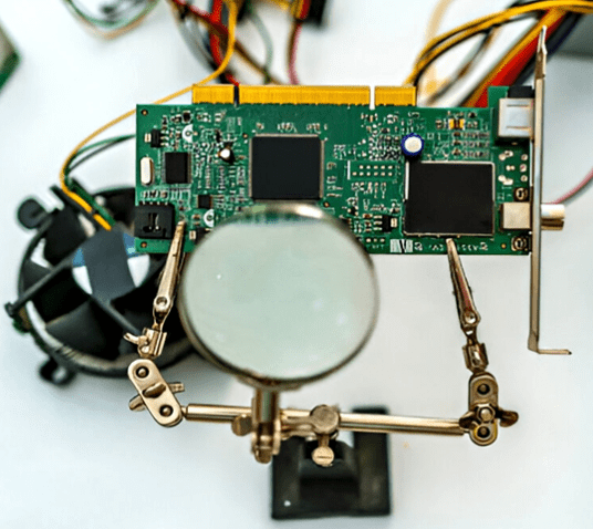
Recommended basic tools for PCB troubleshooting include a multimeter, soldering iron, desoldering pump, and magnifying glass. PCB engineers also use other tools such as power supplies, circuit fixtures, oscilloscopes, and electrical parameter analyzers.
For complex and hybrid PCB designs, advanced equipment such as LCR meters, thermistors, X-ray inspection systems, and circuit testers are sometimes used to guide engineers in locating faulty components deep within the PCB.
Various Methods for Finding Faulty Components
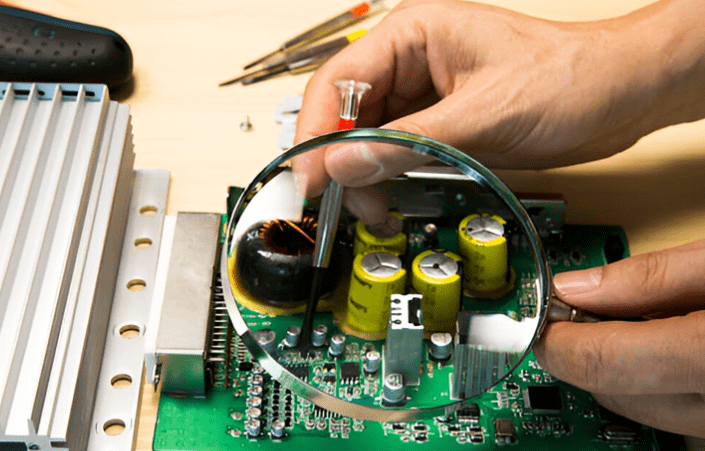
1. Visual Inspection
It is the first and most revealing step in faulty component finding. By looking at the PCB carefully and comparing it with the standard model, the faulty components can be seen. Burn marks, loose or broken components, cracked or swollen capacitors, soldering defects and missing components can be observed by visual inspection. For beginners learning how to find faulty components on PCBs, this step often provides the quickest clues.
2. Electrical Testing Methods
Post visual inspection, if there is no sign of any kind of faulty component, then come the further testing methods. Connect the PCB to the power analyser or circuit jig and observe the electrical & functional parameters of the PCB. Find any sign of degraded output and make a link between the parameters and the respective section or component of the PCB. These measurements are essential in practice when applying how to find faulty components on PCBs through data-driven checks.
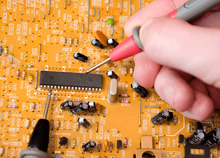
3. Component-based Testing
PCB malfunction is linked directly or indirectly to the dedicated component. Since the PCB works on end-to-end logic, and fault at any part or section definitely affects the overall performance of the PCB. By using a multimeter, LCR meter, oscilloscope and component tester, the faulty component can be identified on the board. This is one of the most detailed techniques for how to find faulty components on PCBs in professional environments.
4. Signal Tracing
PCB components are connected with each other through defined traces. Any discontinuity in the trace breaks the interconnection between the components. Signal tracing is also required to be checked during fault fault-finding process. At first, identify and segregate the power and signal traces in the PCB as both have unique characteristics. Now, check for the end-to-end continuity (source to output) of the trace from one component to another. Following this path is another approach to mastering how to find faulty components on PCBs without missing hidden defects.
5. Thermal Testing
Present PCBs have become more compact in size and more complex in design. It is always indicated on the end product to operate under defined temperature and environmental conditions to avoid thermal runaway of the PCB. During operation, the PCB generates heat and needs to be extracted regularly. Check for the proper heat sink and air ventilation for the PCB. By using thermal cameras, infrared devices and thermometers, the temperature of the PCB and critical components can be checked. Techniques such as these are also valuable when engineers focus on how to find faulty components on PCBs, especially those affected by overheating.
How to Locate Faulty Components on a PCB
Finding faulty components on a Printed Circuit Board (PCB) is a task that combines theoretical knowledge, practical experience, and logical analysis. It is a core skill for engineers and electronics enthusiasts.
Below, I will provide you with a systematic troubleshooting process and methods, ranging from simple to complex.
Step 1: Preparation
Before starting, proper preparation can make the process much more efficient:
- Safety First! Ensure the PCB is powered off, especially for high-voltage boards (like switch-mode power supplies). Large capacitors may hold a charge and need to be discharged first.
- Obtain Documentation: If possible, find the schematic diagram and component layout diagram for the PCB. This is the ideal scenario, allowing you to quickly understand the signal flow and component parameters.
- Basic Tools:
- Multimeter: An essential tool for measuring voltage, resistance, and continuity.
- Magnifying Glass or Microscope: Used for observing tiny cracks, cold solder joints, or PCB trace damage.
- Tweezers: Used for gently moving components to check for looseness.
- Hot Air Gun or Soldering Iron: Used for desoldering and replacing components.
- Experience and Patience: Be patient and follow logical steps. Wild guesses and blindly replacing components often introduce new problems.
Step 2: Visual Inspection
This is the simplest, most direct, and most crucial step. Many faults can be found through careful observation.
- Burnt Marks: Look for any blackened, charred areas on the PCB. Resistors, ICs, and power transistors are common failure points.
- Bulging or Burst Capacitors: Especially electrolytic capacitors. A bulging top or ruptured bottom is a typical sign of failure.
- Cracks or Breaks: Check large inductors, resistors, or cores for physical damage.
- Solder Joint Issues:
- Cold Solder Joint: The joint is not smooth, has cracks, or a grainy appearance.
- Insufficient Solder: The joint surface is rough and dull.
- Solder Bridges: Adjacent solder pads are accidentally connected by solder, causing a short circuit.
- Pin Corrosion or Oxidation: In humid environments, component pins can rust or oxidize, leading to poor contact.
- PCB Trace Damage: Check if the copper traces are scratched, broken, or peeling.
Tip: Tilt the PCB from different angles and use light reflection to get a better view of solder joints and flatness.
Step 3: Basic Multimeter Testing
If the visual inspection reveals no obvious issues, proceed with basic measurements using a multimeter.
1. Resistance Method (Board Powered OFF)
- Measure Power-to-Ground Resistance: Set the multimeter to the resistance (or diode/continuity) mode. With the PCB powered off, measure the resistance between the power input (VCC) and ground (GND).
- Normal Condition: Should have a resistance ranging from a few hundred ohms to several thousand ohms (depending on circuit complexity).
- Abnormal Condition: If the resistance is only a few ohms or close to zero, it indicates a severe short circuit. If the resistance is infinite (open circuit), it indicates an open circuit.
- In-Circuit Component Resistance Measurement: You can directly measure resistors, diodes, inductors, etc., on the board. Note: Due to parallel paths with other components, the measured value might be lower than the nominal value. If the measured resistance is much lower than the nominal value or close to zero, the component is likely shorted. If it reads infinite, and it shouldn’t (like a resistor), it might be open.
2. Continuity Test
- Used to check if PCB traces, vias are connected, if fuses are blown, or if switches are functioning correctly.
Step 4: Power-On Testing (Dynamic Measurement)
Warning: Be extremely careful when powering on the board to prevent electric shock or short circuits. If a short circuit was suspected in the previous step, be extra cautious when applying power.
1. Voltage Method
This is the most commonly used and effective dynamic testing method.
- Check the Power Tree:
- Start from the power input and measure if the voltage is correct (e.g., is the 12V input really 12V?).
- Follow the power path and check the input and output voltages of each voltage regulator (e.g., 7805, 1117, switching regulator ICs).
- Example: A 5V regulator has a normal 12V input, but the output is 0V or significantly lower than 5V. The problem could be the chip itself, a short circuit on its output load, or an issue with its enable pin.
- Check Key Point Voltages:
- Microcontroller/CPU: Check the VCC pins, reset pin, and clock pin voltages.
- Analog Circuits: Check the positive/negative supply pins of op-amps, reference voltage sources.
- Digital Circuits: Check if logic levels are normal (high level close to VCC, low level close to 0V).
2. Temperature Method
- Touch Temperature: Carefully touch (beware of high temperatures!) components, especially ICs, power transistors, and power chips. If a component is abnormally hot, it is likely the culprit.
- Thermal Imager: If available, using a thermal imaging camera can quickly locate abnormal heat spots across the entire board, which is very efficient.
Step 5: In-Depth Analysis and Signal Tracing
When the above methods still cannot locate the fault, more advanced tools and analysis are required.
1. Oscilloscope
A multimeter can only show DC and RMS values, while an oscilloscope allows you to see the “shape” of signals.
- Check Clock Signals: Do the clock pins of microcontrollers and digital chips have normal waveforms?
- Check Reset Signal: Is the power-on timing of the reset signal correct?
- Check Communication Signals: Are there data waveforms on buses like I2C, SPI, UART?
- Check Power Supply Ripple: Is the power quality good? Is there excessive noise?
2. Component Substitution Method
When you highly suspect a specific component (especially ICs, transistors, capacitors) but cannot be 100% sure, replace it with a known good component of the same model. If the circuit returns to normal after replacement, it confirms the original component was faulty.
3. Signal Injection and Tracing
Mainly used for analog circuits (e.g., audio amplifiers).
- Injection: Inject a known test signal (e.g., a sine wave) at the circuit input.
- Tracing: Use an oscilloscope to measure from the input, progressing stage by stage along the signal path, observing where the signal disappears or becomes distorted. The fault lies at that stage.
Summary of Common Faulty Components and Inspection Points
| Component Type | Common Failure Signs | Inspection Methods |
|---|---|---|
| Capacitor | Electrolytic: Bulging, leaking, reduced capacitance, increased ESR. Ceramic: Short circuit (breakdown). | Visual: Bulging. In-Circuit Resistance: Short. Special Tools: Capacitance Meter/ESR Meter. Substitution: Common. |
| Resistor | Increased resistance (open circuit), burnt, color bands unreadable. | In-Circuit Resistance Measure: Value too high or infinite. Visual: Burnt. |
| Diode/Zener Diode | Shorted, open, reverse leakage. | Multimeter Diode Test Mode: Forward should show 0.2-0.7V drop, reverse should show “OL” (infinite). |
| Transistor/MOSFET | Breakdown short (C-E or D-S conduction), open, performance degradation. | Multimeter Diode Test Mode: Check BE/BC/CE (or GS/GD/DS) junctions for correct transistor characteristics. |
| Integrated Circuit (IC) | Overheating, shorted power pins, no output, logic function error. | Voltage Method: Check power, enable, clock, reset. Temperature Method: Check for overheating. Oscilloscope: Check input/output waveforms. Substitution Method: Final confirmation. |
| PCB Itself | Blocked vias, broken traces, lifted pads. | Continuity Test: Carefully measure suspected traces. Visual with Magnification. |
Remember, troubleshooting is a cyclical process of hypothesis, verification, and elimination. Always maintain a clear line of thought. Start with simple possibilities and gradually delve deeper. By doing so, you will successfully find and repair the vast majority of faulty components on a PCB.
The Correct Method for PCB Component Fault Identification
Finding faulty components on a PCB is a technical task aimed at restoring the PCB to normal function. During the fault finding process, some operations on the PCB and modifications to existing components are required. To maintain core product integrity and quality, the following best practices must be followed when locating faulty components on a PCB:
Generally, refer to the relevant PCB standards and authorized layout. Arbitrary assumptions and application of any logic can lead to incorrect results.
When handling faulty PCBs, always adhere to proper safety procedures. Turn off the power and allow the PCB to fully discharge. Wear an anti-static wrist strap and ensure the workstation is properly grounded.
Document and organize the entire process, summarizing key points for future reference.
Start with common sense, then gradually apply more complex terminology. Do not use complex logic to find faults from the outset. Often, faults can be found through simple logic.
Replace the faulty component with a new one. Never attempt to repair or reuse a faulty component.
If feasible, avoid over-processing and testing the PCB. Over-processing degrades the core quality of the PCB.
Summary
While troubleshooting faulty components can take time, anyone can become proficient in this field with the right tools, more practice, and a broader skill set. In the future, the PCB manufacturing industry will see the emergence of more advanced tools and methods for the timely detection and identification of faulty components.


0 Comments