
Introduction
FCT (Functional Circuit Test) is a critical quality validation step in the Printed Circuit Board Assembly (PCBA) manufacturing process. It involves simulating the actual operating conditions of a circuit board to verify whether its functions and performance meet design specifications. As electronic devices evolve toward higher performance, greater integration, and multifunctionality, FCT has become an indispensable method to ensure product reliability and stability. This test provides the Unit Under Test (UUT) with simulated operating environments—including excitation signals and loads—enabling it to operate in various designed states. Parameters such as voltage, current, power, communication protocols, and signal integrity are then measured to validate whether the PCBA functions as intended .
The importance of FCT testing in modern electronics manufacturing cannot be overstated. Industry data indicates that comprehensive FCT testing can reduce field failure rates of PCBAs by up to 40%, significantly enhancing product market competitiveness and customer satisfaction . Particularly in high-reliability sectors such as automotive electronics, medical devices, and aerospace systems, FCT serves as a crucial gatekeeper for quality assurance. It not only identifies manufacturing defects but also validates the correct interaction between hardware and embedded software—an area where traditional inspection methods like ICT (In-Circuit Test) and AOI (Automated Optical Inspection) often fall short . With the rapid development of 5G, IoT, and AI technologies, FCT methodologies continue to advance, providing the electronics manufacturing industry with increasingly sophisticated and efficient solutions .
1. What is FCT Testing in PCB?
FCT (Functional Circuit Test) is a key testing method in PCBA manufacturing specifically designed to validate the functional integrity of an assembled circuit board under simulated real-world operating conditions. Unlike tests that focus solely on static electrical characteristics, FCT is a dynamic testing approach that applies appropriate excitation signals and load conditions to the PCBA, bringing it into an operational state. The output responses are then measured and compared against design specifications to determine pass/fail status . This testing encompasses basic parameters such as voltage, current, power, frequency, and duty cycle, as well as complex functional validations including communication interfaces, sensor responses, and display effects .
From a technical architecture perspective, a complete FCT test system comprises four core components: the system control center (typically a PC, MCU, or embedded processor), the control execution unit (responsible for establishing the test environment), the parameter measurement unit (collects various analog and digital quantities), and the data processing and output unit . Modern FCT systems often employ modular designs, allowing flexible configuration based on specific test requirements, which significantly enhances system adaptability and scalability. The control methodology has evolved from early manual operations to contemporary fully automated systems, greatly improving test efficiency and accuracy .
FCT testing is fundamentally different from other forms of testing. It differs from ICT, which primarily verifies circuit connectivity and component values, and from AOI, which focuses on solder quality inspection . The core value of FCT lies in its ability to validate the functional integrity of the entire circuit board as a system, including the proper interaction between hardware and embedded software . For instance, when testing a smart speaker PCBA, FCT would not only check if the power circuit functions correctly but also validate audio output quality, Bluetooth connection stability, and key response accuracy. This end-to-end validation makes FCT the final critical quality checkpoint before a PCBA leaves the factory, directly determining the final product’s reliability and user experience .
2. The Role of FCT Testing in PCB Manufacturing
FCT testing serves as a quality gatekeeper in the PCBA manufacturing process, with its role spanning from prototype verification to mass production. During the new product introduction (NPI) phase, FCT systems validate the feasibility of design solutions, identify potential design flaws, and provide data support for design optimization . In the mass production phase, FCT is responsible for ensuring that every PCBA shipped from the factory meets functional specifications, preventing defective products from reaching the market, thereby reducing after-sales repair costs and protecting brand reputation .
From a quality assurance perspective, FCT provides final functional validation that other test methods cannot replace. Even if a PCBA passes ICT (verifying component values and solder connections) and AOI inspection (verifying component placement and solder quality), defects that only manifest under actual operating conditions may still exist . These can include timing issues, signal integrity problems, firmware defects, electromagnetic compatibility issues, and interaction problems between components. By simulating real-world usage scenarios, FCT effectively uncovers these potential flaws, ensuring product reliability in the hands of end-users .
In the manufacturing workflow, FCT testing is typically positioned at the end of the production line, serving as the final test step before PCBA shipment. A standard test flow includes: program burning (writing firmware into the microcontroller), ICT testing, FCT testing, and necessary aging tests . This arrangement allows FCT to comprehensively assess the overall quality status of the PCBA after it has undergone all previous processes. The test data can also be fed back to production departments in real-time, helping to quickly identify process issues and achieve closed-loop quality control of the manufacturing process .
For products of varying complexity, the depth and breadth of FCT testing can be flexibly adjusted. For consumer electronics, testing might focus on basic functions and user experience; for high-reliability products like automotive electronics or medical devices, testing is more rigorous, including environmental stress tests and accelerated life testing. This flexibility allows FCT testing to adapt to diverse manufacturing needs, making it an indispensable part of the modern electronics manufacturing system .
3. How FCT Testing Works
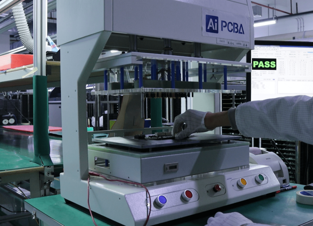
The core principle of FCT testing is based on a closed-loop testing concept that simulates the actual operating environment. The test system applies precisely controlled excitation signals (inputs) to the UUT (Unit Under Test) through hardware interfaces, while simultaneously monitoring the PCBA’s responses (outputs). The measured results are then compared against predefined acceptable ranges to determine whether the PCBA’s functions are normal . This process involves multiple stages, including signal generation, data acquisition, result analysis, and decision-making, requiring close collaboration between hardware and software.
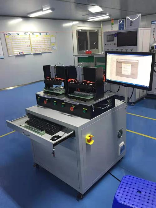
At the hardware level, a typical FCT test system includes an excitation generation module (produces test signals), a data acquisition module (measures PCBA responses), a power management module (provides operating power), and a control processing module (coordinates the entire test process) . These modules connect to the test points on the PCBA via a test fixture, forming a complete test path. Modern FCT systems often adopt standardized architectures like PXI or LXI to ensure measurement accuracy and system stability, while also facilitating maintenance and upgrades.
On the software side, FCT test systems rely on a Test Program Set (TPS) to define specific test procedures, parameter limits, and judgment logic . Test programs are typically written in specialized development environments (such as LabVIEW or TestStand), providing user-friendly interfaces and comprehensive data management functions. Advanced FCT systems also integrate data analysis and report generation capabilities, enabling statistical analysis of test results, fault trend analysis, and providing data support for process improvement .
The execution of an FCT test follows a strict procedural standard. When testing begins, the system first performs a self-check to ensure its own normal status. It then powers up the PCBA via the test fixture and initializes it. Next, it executes each test item in a preset sequence, such as power characteristic tests (voltage, current, power consumption), digital function tests (GPIO, communication interfaces), analog function tests (sensor readings, signal quality), and system function tests (overall behavior verification) . Each test item generates a pass/fail result, and the system ultimately produces a comprehensive test report to support quality decisions. This structured testing approach ensures the comprehensiveness of the evaluation and the consistency of the results .
4. Defects Detectable by PCB FCT Testing
FCT testing can identify various types of PCBA defects, covering aspects from basic electrical characteristics to complex system functions. In terms of power management, FCT testing can detect issues such as poor voltage regulation, insufficient current output capability, excessive power supply noise, and abnormal power consumption . For example, when testing a power module, the FCT system simulates various load conditions to verify whether the output voltage remains within specified tolerances, thereby identifying design or manufacturing defects like insufficient filtering or unstable feedback loops.
In the realm of signal integrity, FCT testing can identify dynamic defects such as timing violations, signal distortion, noise interference, and excessive jitter . For high-speed interfaces (like USB, PCIe, MIPI), FCT testing can validate whether the signal quality meets specification requirements—something static testing cannot accomplish. For instance, in network equipment PCBA testing, the FCT system sends data packets of a specific format and then checks the bit error rate at the receiving end to assess the integrity of the high-speed signal.
Table: Main Types of Defects Detectable by FCT Testing
| Defect Category | Specific Defect Examples | Detection Method | Impact Analysis |
|---|---|---|---|
| Power-Related Defects | Poor voltage regulation, high ripple noise, abnormal power consumption | Load regulation test, dynamic response test | Reduced system stability, component overheating damage |
| Signal Integrity Defects | Timing violations, signal distortion, excessive jitter | Eye diagram test, timing analysis, bit error rate test | Data errors, communication interruptions |
| Functional Logic Defects | Logic errors, state machine lockups, abnormal control sequences | Truth table verification, state traversal testing | Functional failure, system freeze |
| Software/Firmware Defects | Driver compatibility issues, algorithm errors, interrupt conflicts | Boundary value testing, exception handling testing | Performance degradation, functional abnormalities |
| Component Parameter Deviation | Tolerance accumulation, temperature drift, aging effects | Monte Carlo analysis, temperature cycling test | Parameter drift, reduced reliability |
At the system integration level, FCT testing can also uncover critical issues such as interaction defects between different functional modules, resource conflicts, and timing issues . For example, when testing a smartphone PCBA, the FCT system can simulate scenarios where multiple peripherals operate simultaneously to check if the system experiences deadlocks, resource contention, or performance degradation. These types of defects are difficult to detect in single-function tests but have a direct impact on the user experience.
For embedded software related issues, FCT testing also possesses unique detection capabilities. By running specialized test cases, FCT can expose problems such as driver compatibility issues, algorithm implementation errors, and interrupt handling defects . Particularly for mismatches between firmware and hardware, like GPIO configuration errors, clock setting deviations, and peripheral initialization exceptions, FCT testing can provide accurate diagnostic information, significantly reducing debugging time.
It is important to note that the value of FCT testing lies not only in identifying defects but also in providing detailed diagnostic information to help locate the root cause of problems . Modern FCT systems integrate various debugging interfaces and diagnostic tools, recording the system state when a fault occurs, providing crucial clues for subsequent problem analysis and resolution. This combination of detection and diagnosis makes FCT testing one of the most important quality assurance tools in the PCBA manufacturing process.
5. Benefits of FCT Testing
FCT testing offers significant advantages in PCBA manufacturing, most directly in quality improvement and failure prevention. By comprehensively validating PCBA functionality under simulated real-world conditions, FCT testing can uncover defects missed by other test methods, reducing field failure rates of final products by 30% to 50% . Particularly for complex defects like hardware-software interaction faults, timing issues, and marginal effects, FCT testing has unique detection capabilities. This depth of validation significantly improves product reliability, reduces field failures and after-sales repair needs, and directly enhances brand reputation and customer satisfaction.
From an economic perspective, while FCT testing requires initial investment, it substantially reduces the total cost of quality in the long run. Automated FCT test systems can replace 2-3 manual testers, saving factories approximately $560-$1120 (converted from cited CNY amount) monthly in labor costs . More importantly, detecting defects early dramatically lowers repair costs—identifying and fixing a defect at the end of the production line is only one-tenth to one-hundredth of the cost of repairing it in the field . Furthermore, by providing detailed test data, FCT testing helps manufacturers pinpoint the root causes of process issues, enabling continuous improvement and reducing scrap rates and rework time .
Production efficiency is another major advantage of FCT testing. Fully automated FCT systems enable high-speed parallel testing, simultaneously testing multiple PCBAs (e.g., 8 boards in parallel), increasing test efficiency by 5-10 times compared to manual testing . Automatic recording and analysis of test results also eliminate the need for paper records and manual data entry, speeding up decision-making processes. Moreover, standardized test procedures ensure consistency and repeatability across different operators and shifts, eliminating variations introduced by human factors .
From an engineering optimization viewpoint, the data generated by FCT testing provides valuable resources for product improvement. Detailed test records help engineers understand product behavior under different conditions, identify design weaknesses, and provide direction for optimizing the next product generation . Test data can also be used for Statistical Process Control (SPC), enabling real-time monitoring of manufacturing quality and trend prediction, allowing manufacturers to proactively adjust process parameters to prevent defects rather than just detecting them. This data-driven quality improvement cycle significantly enhances the core competitiveness of manufacturing enterprises .
6. ICT vs. FCT Testing
ICT (In-Circuit Test) and FCT (Functional Circuit Test) are two complementary but distinct testing methods in PCBA manufacturing, each with different focuses and application scenarios. ICT testing primarily verifies at the component level, using test probes to contact test points on the PCBA to check if individual component values are correct, solder joints are good, and circuit connections are proper . It focuses on the static characteristics of the PCBA, such as resistance, capacitance, inductance, and circuit continuity. In contrast, FCT testing verifies at the system level, simulating actual operating conditions to check whether the functionality of the fully assembled PCBA meets design expectations as a whole .
From a test strategy perspective, ICT and FCT play different roles in the manufacturing process and are typically performed sequentially. ICT testing is preventive, aiming to detect manufacturing defects early and prevent PCBAs with fundamental issues from moving to subsequent stages . FCT testing, however, is validative, ensuring the final product meets functional requirements . In the actual production flow, a PCBA usually undergoes ICT first (checking basic connections and component values), followed by FCT testing (validating overall functionality). This combined test strategy achieves comprehensive defect coverage .
Table: Comparison between ICT Testing and FCT Testing
| Aspect of Comparison | ICT Testing | FCT Testing |
|---|---|---|
| Test Focus | Component values, circuit connectivity, solder quality | System-level functionality, performance metrics, hardware-software synergy |
| Test Stage | Early production stage, after SMT or initial soldering | Late production stage, after assembly is complete and ICT is passed |
| Defects Found | Opens, shorts, wrong/missing components, value deviations | Functional abnormalities, timing issues, compatibility problems |
| Test Method | Static parameter measurement, bed-of-nails contact with test points | Dynamic functional validation, simulates actual operating conditions |
| Advantages | High coverage, precise fault localization, suitable for mass production | Realistic simulation, hardware-software co-validation, user experience check |
| Limitations | Requires test points, cannot test functional performance | Complex equipment, long test program development cycle |
The two methods also differ significantly in their defect detection capabilities. ICT testing excels at finding manufacturing defects such as missing components, incorrect placement, solder shorts, and opens . It can accurately measure the values of passive components like resistors, capacitors, and inductors to see if they are within tolerance, and verify the orientation of simple active components like diodes and transistors. FCT testing, on the other hand, excels at identifying functional and performance defects, such as poor power supply regulation, signal distortion, logic errors, and software faults . Particularly for timing-related issues and marginal failure conditions, FCT testing has irreplaceable detection capabilities .
In terms of test efficiency and cost, ICT and FCT also have their own pros and cons. ICT testing requires dedicated bed-of-nails fixtures, involving higher initial investment, but offers fast test speeds, making it suitable for high-volume production . FCT test systems are more flexible, but test program development is complex, and execution time is relatively longer . The optimal quality strategy involves rationally configuring the proportion and depth of both tests based on product characteristics to achieve the best balance of quality, cost, and efficiency. For products with high complexity and high reliability requirements, comprehensive ICT and FCT test coverage is usually necessary; for simple, cost-sensitive products, basic FCT testing might suffice .
Summary
FCT testing, as a critical quality validation step in the PCBA manufacturing process, ensures the reliability, functionality, and compliance of final products by simulating real-world operating environments. As electronic systems advance towards greater complexity, higher integration, and broader application, the role of comprehensive FCT testing becomes increasingly vital. It not only identifies manufacturing defects but also verifies design rationality and the协同 working capability of hardware and software, serving as a bridge between design and manufacturing . Modern FCT test systems integrate advanced technologies such as automated control, precision measurement, data analysis, and artificial intelligence, significantly enhancing testing efficiency and quality assurance capabilities.
Looking ahead, FCT testing technology is moving towards greater intelligence and more comprehensive digitalization. Artificial intelligence and machine learning will enable test systems to automatically optimize test strategies, predict potential failure points based on historical data, and achieve more precise test coverage . Digital twin technology will allow for the validation of test schemes in virtual environments, reducing physical trial-and-error costs. Simultaneously, with the proliferation of IoT and 5G technologies, FCT testing will place greater emphasis on new validation needs such as wireless connection performance, power consumption management, and environmental adaptability .
For electronics manufacturing enterprises, building an efficient FCT testing system has become a key strategy for improving product quality and market competitiveness. A well-designed test plan not only reduces after-sales costs but also accelerates time-to-market and enhances brand reputation . Faced with an increasingly complex product ecosystem and diverse application scenarios, FCT testing technology will continue to evolve, providing a solid quality guarantee for the development of the electronics industry and promoting the transformation of technological innovation into reliable products .


0 Comments