




If you’ve ever picked up a freshly assembled circuit board, plugged it in, and nothing happened — no blinking LED, no serial output, just silence — there’s a good chance the board wasn’t broken. It just hadn’t been programmed yet.
This is one of those topics that sounds simple until you actually sit down to do it. So let’s walk through what “programming a PCB” really means, the tools you’ll need, and the mistakes that trip people up the most.
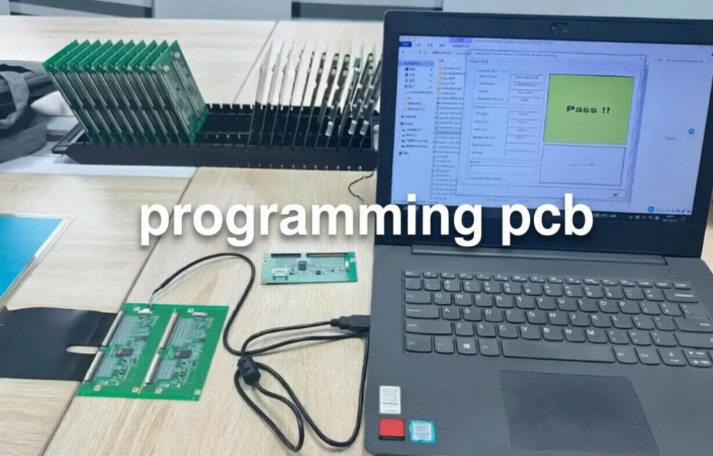
Wait — You are Not Programming the Board Itself
Here’s the thing that confuses a lot of people when they first hear the phrase: a PCB is a piece of fiberglass with copper traces on it. It doesn’t store software. It doesn’t run code.
What you’re actually programming is one or more chips on that board. The most common candidates are:
- Microcontrollers (MCUs) — the workhorses of embedded systems. Think STM32, ESP32, ATmega, and so on. They need firmware loaded before they can do anything useful.
- FPGAs and CPLDs — configurable logic devices that require a bitstream file to define their behavior.
- Flash memory chips — sometimes the firmware lives not on the MCU itself, but on a separate SPI or I²C flash chip that the processor reads from at boot.
- Configurable ICs — some sensors, communication chips, or power management ICs need configuration data written to their internal registers during assembly.
So when a hardware team says “we need to program the PCB,” what they really mean is: “we need to load software onto the programmable device(s) on this board so it actually functions.”
It’s a small distinction, but it matters — especially when you’re debugging something and trying to figure out where the problem is.
Why Programming Is a Bigger Deal Than You’d Think
Some people treat programming as an afterthought — something you do at the very end, right before the board goes out the door. And technically, that’s often when it happens. But in practice, how you approach programming can make or break your timeline.
Here’s why it matters:
1. It’s your first real functional test. A board can look perfect under a microscope — every solder joint clean, every trace intact — and still be a brick without firmware. Programming the board is often the first moment you find out whether the hardware actually works.
2. It catches manufacturing defects early. If a board can’t be programmed at all, there’s usually a hardware problem underneath. A broken solder joint on the programming header, a missing decoupling capacitor, a reversed connector — these things tend to show up during the programming step, which makes it an unofficial (but very effective) quality checkpoint.
3. It gets complicated at scale. Prototyping a single board? You can hand-solder a header and flash it with a USB cable in five minutes. Now imagine doing that for 500 boards on a production line. Suddenly you need fixtures, automated scripts, version control for firmware files, and a process that’s repeatable.
The Tools of the Trade
Let’s talk about what you actually need to program a PCB. The specific tools depend on what’s on your board, but the general categories are pretty consistent.
The Programmer (Hardware)
This is the physical device that sits between your computer and the target chip. Common types include:
- JTAG/SWD debuggers — the most universal option. If your board has a microcontroller, there’s a good chance it supports JTAG or SWD (Serial Wire Debug, ARM’s compact alternative to JTAG). These tools let you write firmware, step through code, and inspect registers in real time.
- Dedicated flash programmers — for boards that use external SPI or I²C flash chips, you’ll sometimes use a standalone programmer that clips onto the chip or connects via a test point.
- USB-to-serial adapters — if your MCU supports UART-based bootloader programming (very common with ESP32, many STM32 parts, and Arduino-compatible chips), a simple serial adapter is all you need.
The Software
Every programmer comes with its own software toolchain. Some are polished and user-friendly; others feel like they were written in 1998 and haven’t been touched since. Regardless of which one you’re using, the software needs to:
- Detect the target chip
- Accept a firmware file (usually in
.hex,.bin, or.bitformat) - Write the file to the chip’s memory
- Verify that the write was successful
The Firmware File
This is the actual code — the compiled output of your embedded software project. It might come from your own development team, or it might be provided by a chip vendor as part of a reference design. Either way, version control is critical. Loading the wrong firmware onto the wrong board revision is one of the most common (and most avoidable) production errors.
The Physical Connection
This is where things get practical. Your board needs some way to physically connect to the programmer. The most common options:
- Programming headers — a small pin header (e.g., 2×3 for JTAG, 4-pin for SWD, or 4-pin for UART) placed on the PCB during layout. This is the most reliable approach.
- Test pads — smaller pads placed on the board for use with pogo pin fixtures. Common in production environments where you don’t want a permanent header taking up space.
- ISP (In-System Programming) pads — some chips support programming through their existing communication pins, with no dedicated header at all.
A Step-by-Step Walkthrough
Here’s how the programming process typically works, from a practical standpoint:
Step 1: Identify the target device
Pull up your schematic and BOM. Which chip on the board needs to be programmed? What interface does it use — JTAG, SWD, SPI flash, UART bootloader? This seems obvious, but on complex boards with multiple programmable devices, it’s easy to lose track.
Step 2: Prepare the firmware
Make sure you have the correct firmware file for the specific board revision you’re working with. Check the version number. Check the build date. Check the file hash if your workflow supports it. Firmware version mismatches are the silent killers of production lines.
Step 3: Connect the programmer
Attach your programming tool to the board through the appropriate header or test points. Double-check:
- Pin orientation (yes, people still get this wrong)
- Voltage levels (is the programmer configured for 3.3V? 1.8V? Don’t guess.)
- Signal routing (are the right pins connected to the right signals?)
Step 4: Power the board
Some programmers can supply power to the target through the programming cable; others require the board to be powered separately. Whatever the case, make sure the board has stable, clean power before you attempt to write anything. Programming under marginal voltage conditions is a recipe for corrupted firmware and wasted hours.
Step 5: Erase, write, verify
The standard workflow is:
- Erase the existing contents (if necessary)
- Write the new firmware
- Verify by reading back the contents and comparing them to the source file
Skipping the verify step is tempting when you’re in a hurry. Don’t. A verify failure now is a field return later.
Step 6: Test the board’s behavior
Programming completed successfully? Good. Now does the board actually work? Look for the expected boot sequence — LED patterns, serial output, communication handshakes, sensor readings. The programming tool can confirm the bits were written correctly; only a functional test confirms the firmware is doing what it’s supposed to do.
Troubleshooting: When Things Go Wrong
Even with a solid process, programming issues come up. Here are some of the most common ones and what usually causes them.
“No device detected”
The programmer can’t see the chip at all. This is usually one of three things:
- Wiring error (wrong pin mapping or reversed connector)
- The chip isn’t powered
- A reset or enable pin is being held in the wrong state by another component on the board
“Programming failed at XX%”
The write started but didn’t finish. Possible causes include:
- Unstable power supply during the write process
- A marginal solder joint on the programming header
- Signal integrity issues on long or poorly routed programming traces
- The programmer’s clock speed being too aggressive for the target
“Programmed successfully, but the board won’t boot”
This is the most frustrating scenario. The programming tool says everything is fine, but the board is dead. Common culprits:
- Wrong firmware version for the board hardware
- Clock configuration mismatch (the firmware expects an external crystal that isn’t working)
- Missing pull-up or pull-down resistors on boot configuration pins
- The firmware is running, but the debug output is going to the wrong UART
Prototyping vs. Production: Two Very Different Worlds
How you program a board changes dramatically depending on where you are in the product lifecycle.
During Prototyping
Speed and flexibility rule. You’re probably programming boards by hand, with a debugger plugged in, updating firmware multiple times a day. A loose jumper wire and a USB cable are your best friends. The goal is rapid iteration — get the firmware running, find the bugs, fix them, repeat.
During Production
Now it’s about throughput and consistency. You might be programming hundreds or thousands of boards, and the process needs to be:
- Repeatable — same steps, same firmware, same outcome every time
- Fast — programming time per board directly affects production cost
- Traceable — you need to know which firmware version went onto which board, and when
This is where custom programming fixtures (bed-of-nails or pogo-pin jigs), automated scripting, and firmware version management systems become essential. It’s also where working with an experienced assembly partner pays off — having your programming process integrated into the assembly line saves significant time and reduces the risk of boards being shipped without firmware.
Best Practices That Save Headaches Later
A few habits that seasoned hardware teams swear by:
1. Always label your firmware files clearly. Include the product name, version number, board revision, and date. Something like ProductX_v2.3.1_RevC_20250630.bin is infinitely better than final_new.bin.
2. Design your programming interface into the board from the start. Don’t leave programming pads as an afterthought. Place the header or test pads early in the layout process, and make sure they’re accessible after the board is assembled — even if other components are nearby.
3. Use a consistent programming procedure. Write it down. Every step, every check, every verification. When things go wrong at 2 AM, you’ll be glad you did.
4. Keep power stable during programming. This sounds obvious, but it’s the cause of more corrupted firmware than most people realize. If you’re powering the board through the programmer, make sure the programmer can supply enough current. If you’re powering it externally, make sure the voltage is clean and within spec.
5. Verify every board before it ships. Not just “did the programmer say it succeeded” — but “does the board actually do what it’s supposed to do?” A quick functional test during programming is cheap insurance against returns and support tickets.
Final Thoughts
Programming a PCB isn’t glamorous. It doesn’t get the same attention as layout design or signal integrity analysis. But it’s one of those steps that sits at the intersection of hardware, software, and manufacturing — and getting it wrong can stall an entire project.
The good news is that the fundamentals are straightforward: know your target device, use the right tools, follow a repeatable process, and always verify your work. The rest is just experience.
If you’re at a stage where you’re evaluating partners for PCB assembly and programming, it’s worth asking about their programming workflow — how they handle version control, what fixtures they use, and how they verify results. These details say a lot about the overall quality of an assembly operation.
Because at the end of the day, a perfectly designed, perfectly manufactured PCB is just a piece of fiberglass — until someone loads the right firmware onto it.



0 Comments