




Basic PCB testing usually starts with the power off. You check for visible damage, burnt components, broken traces, suspicious solder joints, short circuits, open circuits, and continuity problems. That is the right place to begin, because many serious faults can be found before the board is ever powered.
But not every PCB fault shows up in a power-off test. Sometimes the board looks clean. There is no obvious short between power and ground. The fuse appears fine. The traces look normal. The components do not seem burned. Then you apply power, and the board still refuses to start.
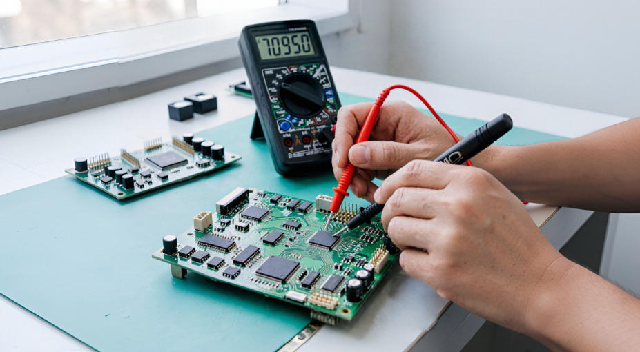
That is where powered testing becomes useful.
Powered PCB testing means using a multimeter while the circuit board is energized. Instead of only checking whether two points are connected, you start checking whether the right voltage is actually reaching the right part of the circuit. You follow the power path, compare expected and actual voltages, and narrow the fault to a smaller section of the board.
This guide is an advanced follow-up to basic PCB testing. It focuses on how to test a PCB with power on, how to check voltage rails, how to test voltage regulators, and how to use simple voltage readings to understand where the circuit stops working.
A multimeter will not show every possible PCB problem. It cannot properly display high-speed communication signals, clock waveforms, switching noise, ripple, or fast startup pulses. For those problems, an oscilloscope may be needed. But for power-related faults, a multimeter is still one of the most useful tools on the bench.
Start with One Rule: Do Not Power a Board Blindly
Before you test a PCB with power on, make sure the board has already passed basic safety checks. Powered testing should not be the first thing you do to an unknown board.
At minimum, inspect the board carefully and check for obvious low-resistance shorts between the main power input and ground. If the board has a direct short, applying power can make the damage worse. It may burn a trace, destroy a regulator, overheat a component, or damage your power source.
For low-voltage DC electronics, such as small control boards, sensor boards, battery-powered devices, development boards, and embedded modules, powered testing is often manageable if you work carefully. If the board connects directly to AC mains, high-voltage power supplies, motor drives, inverter circuits, or unknown power sections, do not treat it like a simple low-voltage PCB. Those circuits can be dangerous, even after power is removed.
If you are not trained to work on high-voltage electronics, do not probe them while powered.
Set the Multimeter Correctly Before You Touch the Board
For most powered PCB troubleshooting, your multimeter should be set to DC voltage mode.
This sounds obvious, but it is one of the most common mistakes. Continuity mode, resistance mode, and diode mode are meant for unpowered circuits. If you use those modes on a live board, the readings may be meaningless. In some cases, you may also damage the meter or the circuit.
For powered testing, the usual setup is simple:
- Set the multimeter to DC voltage mode.
- Connect the black probe to circuit ground.
- Use the red probe to measure the point you want to check.
- Use a proper voltage range if your meter is not auto-ranging.
- Keep the probe tip steady to avoid shorting adjacent pins.
If the board is powered by 12V, you may expect to see 12V, 5V, 3.3V, 1.8V, or another regulated rail depending on the circuit design. If the reading looks strange, first confirm that the meter is in the right mode and the black probe is connected to the correct ground reference.
A surprising number of confusing voltage readings come from a poor ground connection or a wrong meter setting.
Choose a Ground Point You Can Trust
Most PCB voltage measurements are made with reference to ground. That means the black probe should stay on a known ground point while the red probe moves through the circuit.
Good ground points often include:
- the negative input terminal
- a test pad marked GND
- the negative side of a large input capacitor
- a large ground plane pad
- a connector shield, if it is actually connected to ground
Do not assume that every metal part is ground. Mounting holes, heatsinks, shields, and chassis points may not be connected the way you expect. On some boards, there may also be isolated sections where one side of the circuit does not share ground with the other side.
If your readings do not make sense, check the ground reference before assuming the PCB is faulty.
How to Check PCB Voltage with a Multimeter
The basic method for how to check PCB voltage with a multimeter is straightforward: put the meter in DC voltage mode, place the black probe on ground, and use the red probe to measure points along the power path.
The important part is not just taking one reading. The important part is taking readings in the right order.
Instead of probing random components, follow the path that power normally takes through the board. A typical sequence looks like this:
- Input connector
- Fuse or input protection device
- Reverse-polarity protection diode or MOSFET
- Regulator input
- Regulator output
- Main voltage rail
- Load side of the circuit
- Power pins of important ICs
For example, imagine a PCB that takes 12V at the input and uses a regulator to create a 5V rail. A healthy power path may look like this:
- 12V at the input connector
- 12V after the fuse
- 12V at the regulator input
- 5V at the regulator output
- 5V at the IC or module that uses that rail
If you see 12V at the input connector but 0V after the fuse, the regulator is not the first thing to suspect. The problem is probably around the fuse or input protection stage.
If you see 12V at the regulator input but 0V at the regulator output, then the regulator section becomes more interesting.
If you see 5V at the regulator output but only 2V at the IC, the fault may be between the regulator and the load. That could mean a cracked solder joint, damaged trace, bad via, ferrite bead, inductor, connector, or series resistor.
This is the main idea behind powered PCB troubleshooting: find the first point where the expected voltage stops being correct.
Follow the Power Path Instead of Guessing
A circuit board is easier to troubleshoot when you think of it as a chain. Power enters the board, passes through protection parts, reaches one or more regulators, becomes different voltage rails, and then powers ICs, sensors, displays, relays, motors, or communication modules.
If the board is dead, do not start by replacing random components. Start by asking a simpler question: where does the voltage disappear?
Measure one point, then the next. Compare the two. If one side of a component has the expected voltage and the other side does not, you have found a useful clue.
For example:
- If a fuse has voltage on one side but not the other, the fuse may be open.
- If a connector has voltage before it but not after it, the connector or solder joint may be bad.
- If a MOSFET has input voltage but no output voltage, it may not be turned on, or it may be damaged.
- If a regulator has a good input but a missing output, you need to check its enable pin, load condition, and temperature.
This approach is slower than guessing, but it is much more reliable.
How to Troubleshoot PCB Voltage Rails
A voltage rail is a supply line that powers part of a PCB. Common rails include 12V, 5V, 3.3V, 1.8V, 1.2V, and sometimes negative voltages depending on the circuit.
Learning how to troubleshoot PCB voltage rails is one of the most useful skills in board repair. Many PCB faults are not mysterious at all. A chip may not work simply because its supply rail is missing, too low, unstable, or not reaching the correct pin.
When checking a voltage rail, do not only ask whether voltage exists. Ask whether the reading fits the circuit:
- Is the rail present?
- Is the value correct?
- Does the voltage stay stable?
- Does the rail reach the actual load?
- Does the voltage drop when the load turns on?
If the Rail Is 0V
A 0V rail usually means power is not reaching that point, or the regulator is not producing output. The cause may be upstream, such as an open fuse, missing input voltage, damaged trace, failed connector, or protection MOSFET that is not conducting.
It may also be intentional. Some regulators stay off until an enable signal tells them to start. If the enable pin is low, the regulator may not be faulty at all. It may simply be disabled by the control circuit.
If the Rail Is Too Low
A low voltage rail is one of the most common powered PCB symptoms. For example, a 5V rail may read 1.2V, or a 3.3V rail may sit around 0.8V.
Do not immediately assume the regulator is bad. A rail can be pulled low by a shorted capacitor, damaged IC, overloaded circuit, weak input supply, overheating regulator, or protection mode.
A good next step is to check whether the regulator input is normal. If the input is also low, the problem may be upstream. If the input is correct but the output is low, then check the load side and the regulator control pins.
If the Rail Looks Correct but the Board Still Fails
A correct voltage rail does not prove that the whole board is healthy. It only tells you that DC power is present at that point.
The circuit may still have problems with reset signals, clock signals, communication lines, firmware, oscillators, sensors, drivers, or noisy power that a basic multimeter cannot show clearly. In that case, a scope or a more detailed circuit-level test may be needed.
Still, confirming the power rails first is valuable. It prevents you from chasing signal problems when the real issue is simply missing power.
How to Test a Voltage Regulator on a PCB
Many boards depend on one or more voltage regulators. A regulator may take 12V and create 5V, or take 5V and create 3.3V, 1.8V, or another lower rail. If the regulator does not work, the section it powers may appear completely dead.
The practical way to learn how to test a voltage regulator on a PCB is to check four important points:
- input pin
- output pin
- ground pin
- enable pin, if the regulator has one
Start with the input pin. If the regulator has no input voltage, do not blame the regulator yet. The fault is likely before it. Check the fuse, input connector, protection diode, MOSFET, inductor, or trace that feeds it.
If the input voltage is correct but the output is 0V, look at the enable pin. Many regulators will not turn on unless EN is pulled high. A missing enable signal can make a good regulator look dead.
If the input is correct, the enable pin is active, but the output is still missing or too low, the regulator may be overloaded, in thermal shutdown, damaged, or protecting itself from a downstream short.
If the regulator output is correct but the load side does not receive that voltage, the problem may be after the regulator. Look for a broken trace, bad via, cracked solder joint, open ferrite bead, damaged inductor, or failed series resistor.
Use Voltage Drop to Find Bad Connections
Sometimes voltage is not completely missing. It is present, but it is lower than it should be after passing through a connector, fuse, switch, MOSFET, resistor, or solder joint. This is where voltage drop testing becomes useful.
Instead of measuring every point only against ground, you can measure across a component or connection. Put one probe on one side and the other probe on the other side. The meter then shows how much voltage is being lost across that part.
For example, a healthy fuse or short piece of copper trace should normally have almost no voltage drop across it. If you measure a noticeable drop across a fuse, connector, or solder joint under load, that part may have high resistance.
Here are a few common examples:
- 12V on one side of a fuse and 0V on the other side usually means the fuse is open.
- 5V on one side of a connector and 3.6V on the other side may point to a bad connector or solder joint.
- A MOSFET with input voltage but no output voltage may be off, damaged, or missing its gate control signal.
- A rail that drops only when the load turns on may indicate overload, weak supply, or a high-resistance connection.
Voltage drop testing is especially useful because some bad connections look fine when the board is off. They only fail when current actually flows.
Common Powered PCB Faults and What the Readings Mean
The table below shows how common powered PCB symptoms can be interpreted. These are not absolute rules, but they are useful starting points.
| Symptom | What It May Mean | What to Check Next |
|---|---|---|
| Input voltage is missing | Power adapter, cable, connector, or supply issue | Measure the source, input jack, and connector pins |
| Voltage exists before the fuse but not after it | Open fuse or damaged protection part | Check both sides of the fuse and inspect for overload causes |
| Regulator input is normal but output is 0V | Disabled regulator, overload, shorted load, or failed regulator | Check EN pin, output rail resistance, and load side |
| Voltage rail is much lower than expected | Overload, partial short, weak input, or regulator protection | Check regulator input, output load, and hot components |
| Regulator output is correct but IC has no power | Open trace, bad via, ferrite bead, inductor, or solder joint | Measure the rail at both ends of the path |
| Board starts then shuts down | Overcurrent, thermal shutdown, unstable rail, or startup fault | Watch voltage during startup and check current draw |
| Voltage is correct but function still fails | Signal, clock, reset, firmware, or communication problem | Check reset lines, clocks, and use an oscilloscope if needed |
Do Not Ignore the Enable Pin
One of the easiest mistakes in regulator troubleshooting is ignoring the enable pin.
Many modern regulators have an EN, ENABLE, SHDN, or ON/OFF pin. If that pin is not at the correct logic level, the regulator may not produce output even when the input voltage is perfect.
So if you measure a regulator and find:
- input voltage is present
- output voltage is missing
- the regulator is not obviously burned
do not replace it immediately. Check the enable pin first.
If EN is low, the problem may be in the control circuit, power sequencing circuit, microcontroller, pull-up resistor, reset circuit, or another regulator that must start first.
On more complex boards, one missing rail can prevent another rail from turning on. This is why following the power sequence matters.
What a Multimeter Cannot Tell You
A multimeter is excellent for checking DC voltage, continuity, resistance, and basic power distribution. But it has limits.
A multimeter usually cannot show:
- fast voltage spikes
- high-frequency ripple
- switching regulator waveforms
- clock signals
- digital communication data
- short startup pulses
- intermittent glitches that happen too quickly
If all voltage rails are correct but the circuit still does not work, the fault may be outside what a multimeter can easily reveal. At that point, an oscilloscope, logic analyzer, thermal camera, or schematic may be needed.
That does not make the multimeter less useful. It simply means the multimeter is best used as the first powered troubleshooting tool, not the only tool.
A Practical Powered PCB Testing Workflow
If you want a simple workflow, use this order:
- Inspect the board with power off.
- Check for obvious shorts between power and ground.
- Apply power safely, preferably with current limiting.
- Measure the input voltage at the board.
- Check the fuse and input protection stage.
- Measure regulator input voltage.
- Measure regulator output voltage.
- Check the enable pin if the regulator output is missing.
- Measure the voltage rail near the load.
- Compare readings with expected values.
- Find the first point where the voltage becomes wrong.
This workflow keeps you from guessing. It also helps you avoid replacing good components just because they are near the symptom.
FAQ
Can I test a PCB while it is powered on?
Yes, you can test a PCB while it is powered on if it is safe to do so and you use the correct multimeter mode. For powered testing, use DC voltage mode. Do not use continuity, resistance, or diode mode on a live board.
Where do I place the black probe when checking PCB voltage?
In most low-voltage DC circuits, place the black probe on circuit ground. A GND test pad, negative input terminal, or negative side of a large input capacitor is often a good reference point.
Why does my 5V rail read only 1V or 2V?
A low rail does not always mean the regulator is bad. The rail may be overloaded, shorted by a downstream component, affected by a weak input supply, or limited by regulator protection. Check the regulator input, enable pin, and load side before replacing parts.
Can a multimeter find every PCB fault?
No. A multimeter is very useful for power faults, voltage rails, continuity, and basic component checks. It cannot clearly show fast signals, ripple, digital data, clock problems, or short glitches. For those issues, you may need an oscilloscope or other test equipment.
Conclusion
Powered PCB testing is the next step after basic power-off checks. Once you know the board does not have an obvious short, a multimeter can help you follow the power path and find where the circuit stops behaving normally.
The key is to work in order. Start at the input, check protection parts, measure regulator input and output, verify voltage rails, and confirm that power reaches the actual load. If a voltage rail is missing or too low, do not jump to conclusions. Look at the upstream supply, enable signals, downstream load, and voltage drops across connectors or protection parts.
A multimeter will not solve every advanced PCB problem, but it can quickly answer one of the most important questions in troubleshooting: is the right voltage reaching the right place?



0 Comments